14
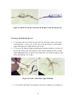
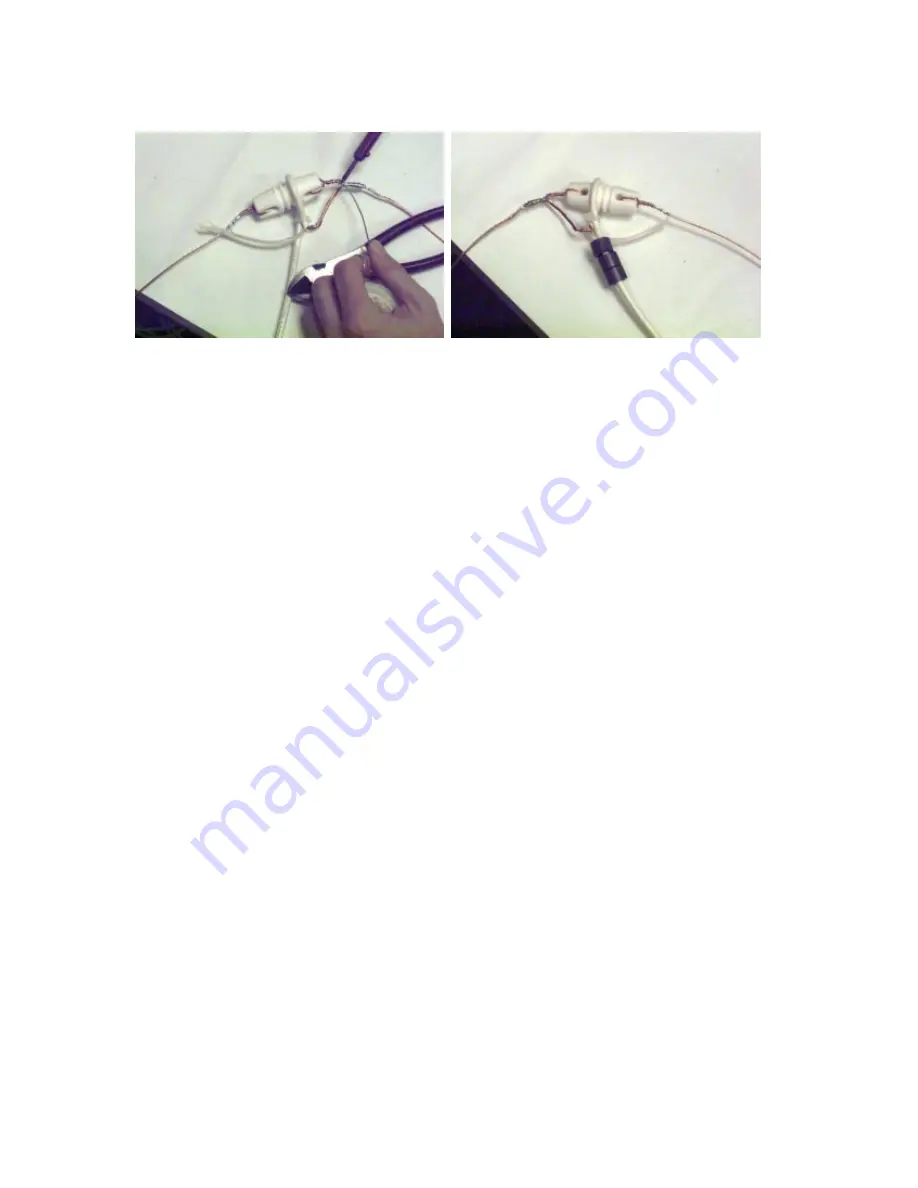
Figure 5. Solder the shielding and center conductor to the copper wires.
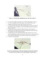
Figure 6. Install the ferrite toroid cores.
Installing the Toroids and Connectors
1.
o
For each dipole, slide 3 ferrite toroids cores up the cable to the very top of the
coax near the dipole. Secure them all in a row with tape and a tie wrap. Be sure this is
secure because they may slide down the coax after the antenna is up (Figure 6).
2.
o
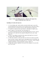
Install the F-connector on the coax feed line to each dipole. To install, remove
about 3/4 inches (2 cm) of the outer coax casing (Figure 7a).
3.
o
Carefully unbraid about half of the exposed shielding (about 3/8 inch (1 cm) and
fold it back over the other half of the copper shielding and over the outer casing
(Figure 7b).
4.
o
Remove the insulation around the center conductor leaving about 1/2 inch (1.3
cm) of bare center conductor (Figure 7c, 7d).
5.
o
Push the F-connector over the end of the coax and twist on as tightly as possible.
The teeth of the F-connector will bite into the shielding that has been folded back and
this will provide good contact for ground. About 1/8 - 1/4 inch (0.3- 0.6 cm) of center
conductor should stick out of the end of the F-connector (Figure 7e).
6.
o
Repeat this connector installation for each end of the long piece of coaxial cable
(the 1
λ
coax cable).
Summary of Contents for RJ1.1
Page 1: ...JOVE RJ1 1 Antenna Kit Assembly Manual...
Page 3: ...2...
Page 5: ...4...
Page 7: ...6...
Page 8: ...7...

