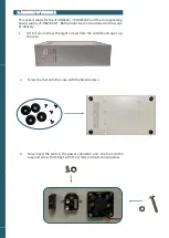
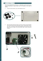
background image


4.


Now, mount the power supply into the case. Therefore, you have to 


screw it from the bottom of the case with the big silver screws.
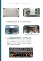
 

5.


Now,  screw  the  fan  control  next  to  the  Power  Supply  with  the


remaining  black  screws  and  connect  the  fan  to  the  connector 


provided for this purpose.
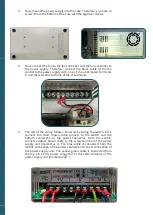
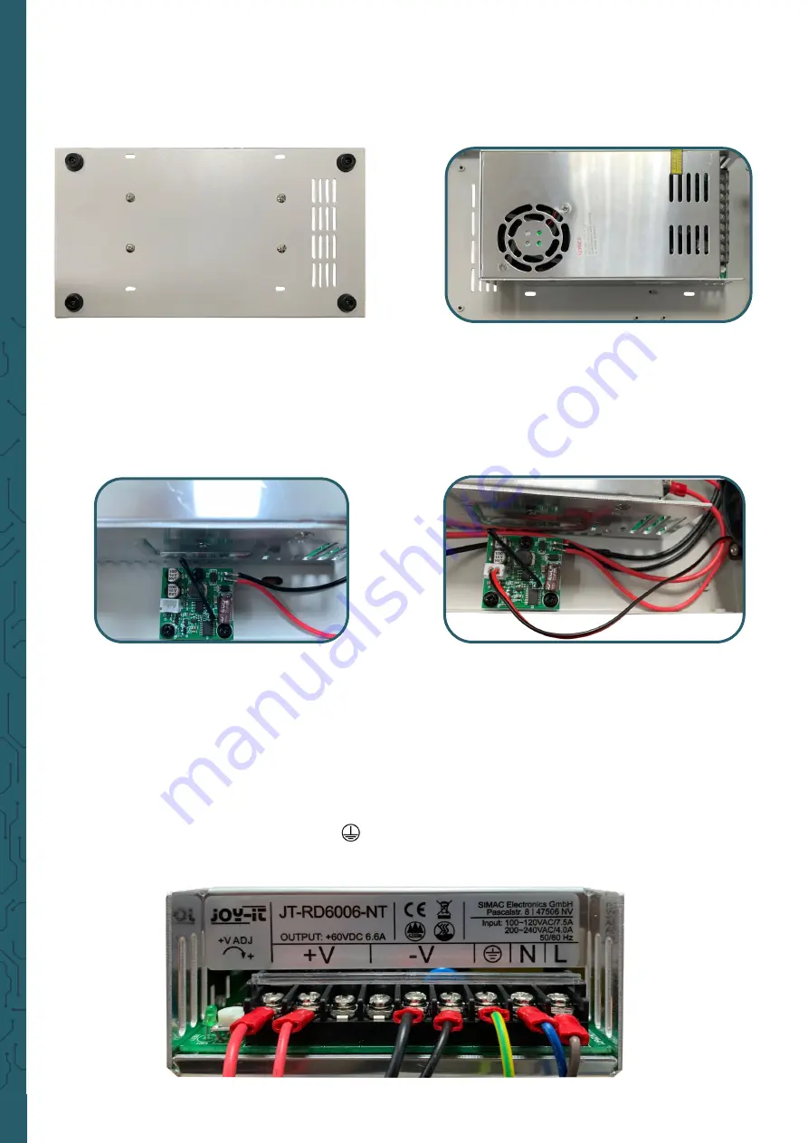
 

6.


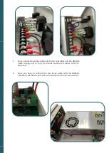
This is followed by the wiring. You start by wiring the switch. First, 

connect  the  short  brown  cable  (phase)  to  the  switch  and  the 


bottom  connection  of  the  power  connector.  From  the  switch, 


connect  another  brown  cable  to  the  screw  terminal  of  the  power 

supply  unit  (marked  as  L).  The  blue  cable  is  connected  from  the 

middle connection of the power connector to the N connection of 

the  power  supply  unit.  The  yellow

-

green  cable  is  connected  from 

the  top  pin  of  the  power  connector  to  the  earth  terminal  of  the 

power supply unit (marked as   


 ).


Summary of Contents for 4250236820477

Page 1: ...e is available in two versions version A and B These versions differ by a lead out of the temperature sensor which only version B features This case is made for an additional power supply which allows...

Page 2: ...T Both products are not included in the scope of delivery 1 First of all unscrew the eight screws from the outside and open up the case 2 Screw the feet onto the case with the black screws 3 Now inser...

Page 3: ...wiring You start by wiring the switch First connect the short brown cable phase to the switch and the bottom connection of the power connector From the switch connect another brown cable to the screw...

Page 4: ...e fan controller and the RD6006 power supply unit to the V terminals and the red cables to the V terminals 8 Now you have to connect the last loose cable with the RD6006 Therefore the black cable will...

Page 5: ...of the RD6006 NT with the help of the fine tuning potentiometer You can see your adjustment at the input voltage of your RD6006 RD6006P Ideally the RD6006 RD6006P has an input voltage of 65 V to be ab...

Page 6: ...the scope of delivery 1 Screw the feet onto the case with the black screws 2 Now place the switch the power connector the fan control and the fan in the enclosure and screw them in place with the sil...

Page 7: ...ew terminal of the power supply unit marked as L The blue cable is connected from the middle connection of the power connection to the N connection of the power supply unit The yellow green cable is c...

Page 8: ...ed between IN on the RD6006 and V on the power supply and the red cable between IN on the RD6006 and V on the power supply 7 You can also connect the connector from the temperature sensor lead out if...

Page 9: ...of the RD6006 NT with the help of the fine tuning potentiometer You can see your adjustment at the input voltage of your RD6006 RD6006P Ideally the RD6006 RD6006P has an input voltage of 65 V to be ab...

Page 10: ...hold quantities 1 Possibility of return at our company location during our opening hours Simac Electronics Handel GmbH Pascalstr 8 D 47506 Neukirchen Vluyn 2 Possibility of return nearby We will send...

Reviews: