background image

 217

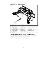
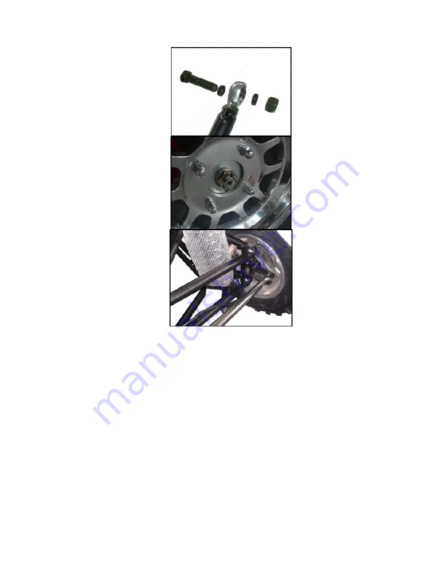
4.Attach tie rod and front wheel 


Summary of Contents for JNSZ1100SVB

Page 1: ...ANT SAFETY INFORMATION MINIMUM RECOMMENDED OPERATOR AGE FOR OFF ROAD USE ONLY This vehicle is designed and manufactured for off road use only USA only It does not confirm to federal motor vehicle safe...

Page 2: ...e features and operation of this vehicle It also includes basic maintenance and inspection procedures If you have any questions regarding the operation or maintenance of your vehicle please consult a...

Page 3: ...TO DRIVE 19 Before you drive your Off high way recreational vehicle for the first time we urge you to 19 Before each drive be sure 19 Protective Apparel 19 Drive Training 20 Age Recommendation 20 No A...

Page 4: ...TRANSSMISSION ILLUSTRATION 156 1 CASE ACCESSORY 156 2 COUNTERSHAFT 158 3 INPUT SHAFT ASSY 160 4 SHIFT FORK SHIFT FORK SHAFT 162 5 SHIFT CONTROL MACHANISM 164 6 DRIVEN GEAR ASSY SPEED REDUCER 167 3 CH...

Page 5: ...and foam cover option 207 29 luxury absorber shock option 208 Wearing parts 209 1 Body 209 2 Engine 210 3 Transmission 211 4 Standard part 212 PREPARATION ATTACH INSTRUCTION 213 1 Remove Packing 213 2...

Page 6: ...Warranty policy...

Page 7: ......

Page 8: ......

Page 9: ......

Page 10: ......

Page 11: ......

Page 12: ......

Page 13: ......

Page 14: ......

Page 15: ......

Page 16: ...contains important safety and maintenance information Failure to follow the warnings contained in this manual can result in serious injuries Be sure to follow the recommended maintenance schedule and...

Page 17: ...ctions how to use this Go Kart correctly and safely This entire manual is filled with important safety information please read it carefully 3 IMPORTANT SAFETY INFORMATION Your Off high way recreationa...

Page 18: ...y reduce your ability to make good judgments and driver safely Don t Drink and drive Alcohol and driving don t mix Even one drink can reduce your ability to respond to changing conditions and your rea...

Page 19: ...The labels are considered permanent parts of the Off high way recreational vehicle If a label comes off or becomes hard to read contact your dealer for warning labels replacements...

Page 20: ...motorcycle helmet with chin strap tightened securely eye protection and other protective clothing y You don t have any alcohol or drugs in your system Protective Apparel For your safety we strongly re...

Page 21: ...r with how this Off high way recreational vehicle works and handles To build skills Practice driving the Off high way recreational vehicle in a safe area do not drive in rough terrain until you get ac...

Page 22: ...t also for comfort Because any a breakdown or even a flat tire can be a major inconvenience If your Off high way recreational vehicle has overturned or has been involved in a collision do not drive it...

Page 23: ...e rod housing for wear Check the fittings for looseness Replace or tighten as needed 7 SAFE DRIVING PRECAUTIONS Off Road Use Only You Off high way recreational vehicle and its tires are designed and m...

Page 24: ...nal vehicle Always keep both hand on the steering wheel and both feet on the foot controls of you re Off high way recreational vehicle during operation Control Speed Driving at excessive speed increas...

Page 25: ...rain Failure to use extra care when operating on excessively rough slippery or loose terrain could cause loss of traction or vehicle control which could result in an accident including an overturn Do...

Page 26: ...ngine oil SAE 10W 30 Gear oil GL 4 75W 90 CAPACITIES Maximum load 250kg Fuel tank 21 5L Engine oil 3500ml Gear oil 2000ml Coolant 6000ml Starting 5s Climbing 20 25 Battery 12V45Ah Head Light 12V 55 55...

Page 27: ...smoothly and returns to idle when released Do not operate if pedal or engine throttles linkage fail to return to idle If unable to correct the problem through lubrication adjustment or replacement of...

Page 28: ...e will move backwards Switch 6 Ignition Switch Pull firmly up on the park brake lever with your hand until the lever is tight Set shift selector in neutral Insert the key into key switch turn the key...

Page 29: ...lowers than normal See your authorized JOYNER dealer if battery is good and voltmeter still register low charge See figure 8 16 Fuel level gauge The fuel gauge displays approximately how much fuel you...

Page 30: ...s be securely fastened in the position which best affords the operator control of the foot pedals steering wheel and the remote stop button See figure 10 a Pull seat adjustment handle upward to diseng...

Page 31: ...is important for your safety and the safety of others that the tires have correct air pressure Check air pressure in four tires before each use Visually inspect tires for loss of air throughout each d...

Page 32: ...he life of your vehicle Proper operation during this break in period will help assure maximum life and performance from your new vehicle The following guidelines explain proper break in procedures Aft...

Page 33: ...en pressure is 1 0MPa 145psi 2 Adjust the shock refer to the following drawing set up set up S mm P N 40 0 50 6793 Front shock spring specification 115 1563 3518 S mm P N 35 0 11299 155 2551 Rear shoc...

Page 34: ...isassemble the center castle nuts when you replace the front wheels See Fig 17 Tighten the nuts after replacing the wheels Castle nuts Torque 180 5 N M Wheel nuts Torque 70 5 N M 8 Clutch replacement...

Page 35: ...e four bolts in the transmission case you must tighten them according to the prescribed torque 45 55N M See Fig 22 25 Q1840845 GB T70 1 2000 M12 1 75 75 25 S11 3708111 S11 3708110GA Q218B1245 Q1841240...

Page 36: ...ove the six bolts on the Clutch pressure plate now It s clear Caution When fix the six bolts in the Clutch pressure plate you must tighten them according to the prescribed torque 28 N M See Fig 28 32...

Page 37: ...spline shaft into the hole of the Clutch assy fix the six bolts on the Clutch pressure plate tighten them according to the prescribed torque 28 N M See Fig 33 34 FIGURE 30 FIGURE 29 FIGURE 31 FIGURE 3...

Page 38: ...ension B smaller turn the rod to the left Turn the rod to the right to make Dimension B larger After adjusted to desired length tighten the lock nut against the rod end Recheck the dimensions for prop...

Page 39: ...to run out of fuel or use a fuel stabilizer 1 5 Lubricate engine cylinder by removing the spark plug and pour one ounce of clean lubricating oil through the spark plug hole into the cylinder Crank the...

Page 40: ...Do not drain fuel while engine is hot Be sure to move Off high way recreational vehicle outside before draining fuel...

Page 41: ...13 ENGINE WIRING DIAGRAM...

Page 42: ...14 MAIN WIRING DIAGRAM DJ7013 6 3 21 DJ7021 1 5 11 DJ7041 1 5 11 DJ7021 1 5 11 DJ7041 1 5 11 DJ7031 1 5 11 DJ7031 1 5 11 DJ7021 1 5 11 DJ7031 1 5 11 4 4 4...

Page 43: ...Reverse light switch IGN 1 interface flag 2 Head light relay interface flag 2 Fuse 5A IGN 1 Fuse 15A interface flag 2 Spot light switch 1 High beam R High beam L Dipping switch 1 dipped beam R dipped...

Page 44: ...ty please clear the filter cover and replace with a new air filter 17 Engine Lubrication 18 Engine oil replacement You must change the oil in the crankcase after the first 5 hours of operating of your...

Page 45: ...r of engine oil changes you need to replace the engine oil as above 1 6 7 Check the engine oil level charge from 2 1 4 as above if the oil level is lower than L 20 Transmission lubrication 21 Oil repl...

Page 46: ...amage See Fig 41 The coolant should always be topped up since the coolant can evaporate 1 6 13 Put the vehicle on level ground 1 6 14 Turn the coolant cap counterclockwise and open the cap see Fig 16...

Page 47: ...d water Wash any clothing or rags if wet with coolant Recycle or properly dispose of used coolant Harm or damage may occur if use coolant that don t meet the specification 50 standard green coolant an...

Page 48: ...hook down Engine relay Fuel pump relay Fan relay Spot light relay R gear indicator fuse Gauge and indicator fuse Brake indicator fuse Engine fuse ECU normal open circuits fuse Flash fuse Fuel pump fus...

Page 49: ...ead light as the picture 6 Unscrew the screw that fixes the bulb and take off the bulb carefully 7 Disconnect the bulb from the wiring 8 Connect a new bulb with the same specification to the wiring 9...

Page 50: ...3 Take off the bulb you need to replace through turning the bulb counter clockwise about a half round and replace a new one 4 Put all the parts back with reversing step 1 2...

Page 51: ...ing Belt 1 Configuration diagram 1 Water pump pulley 2 Timing belt cover upper 3 Timing belt cover Lower 4 Torsion shock absorber 5 Timing pulley damper 6 Tensioner 7 Crankshaft timing pulley 8 Timing...

Page 52: ...Removing timing belt cover Torque 6 1N m 2 3 Remove tensional vibration damper 2 3 1 Fix the flywheel and prevent the gear ring from rotating 2 3 2 Remove bolt of tensional vibration damper 2 3 3 Ens...

Page 53: ...semble according to original state 2 5 3 Make sure that the crankshaft timing pulley wheel mark is aligned with the mark of the oil pump 2 5 4 Remove the tensioner bolt and take off the tensioner 2 6...

Page 54: ...leaked which makes it necessary to refill the water continuously 2 8 5 2 There are much oil stains on the belt the belt should be replaced for the rubber will be damaged when it is expanded Specifica...

Page 55: ...xhaust camshaft so as to make the positioning groove on the gear be aligned with the positioning pin on the end surface of the camshaft Then use screws to fix the clockwise gear with the torque of 100...

Page 56: ...s the key is to adjust the above mentioned stretcher fastening bolt by widening he spacing tighten the S A fixing bolt of the stretcher with the specified torque of 25 3N m 3 4 Install the baffle of t...

Page 57: ...mper 3 6 Install timing belt cover Install seal strip in the position shown as right figure Install the position 1 and position 2 before cylinder head assembly install position 3 before tighten water...

Page 58: ...ver gasket 3 Camshaft timing pulley 4 Camshaft cover 5 Circular plug 6 Camshaft bearing cap 7 Exhaust camshaft 8 Intake camshaft 9 Oil seal 10 Spring retainer 11 Wave washer 12 Intake camshaft sub gea...

Page 59: ...the timing belt sprocket with a special tool Attention Manufacture a special tool according the right figure The special is necessary to prevent the camshaft to rotate 2 3 Removal of camshaft bearing...

Page 60: ...slave gear 2 6 1 Use the special tool as shown in the right figure Clip the camshaft tightly and turn the gear to keep the bite state of master and slave gear remove the fixing bolts of slave gear At...

Page 61: ...camshaft is to be replaced The air inlet camshaft axial clearance is 0 1 0 170mm The air exhaust camshaft axial spacing is 0 1 0 173mm Limits for operation 0 18mm 2 7 3 Checks on camshaft meshing cle...

Page 62: ...n gear with bolt M5 0 8 Attention Do not damage the surface of the camshaft 3 3 Installation of the camshaft Attention Size of the axial clearance of the camshaft 3 3 1 Smear lubricating oil at the ca...

Page 63: ...t Illustration Keep unbiased with cylinder head end surface after pressing 1 1mm 3 7 Smear engine oil on the oil seal installation port of cylinder head camshaft oil seal edge of blade and outside rin...

Page 64: ...3 9 2 Put new one into the groove on the timing belt cover accurately 3 9 3 Cover the cylinder head with cylinder head cover tighten the bolts according the right figure Torque 6 1N m 4 Routine check...

Page 65: ...the standard and the result 4 4 1 Rotate camshaft to make the cam top valve clearance exceed the standard upwards and gap of valve lifter towards inside 4 4 2 Rotate camshaft and the cam press valve l...

Page 66: ...elected cushion thickness removed cushion thickness measured throttle spacing 0 18mm 2 EX Selected cushion thickness removed cushion thickness measured throttle spacing 0 25mm Reference there are 32 k...

Page 67: ...amshaft 2 3 round and then recheck the valve clearance if valve clearance can t get to the standard repeat4 1 4 4 to adjust the valve clearance 31 Cylinder head 1 Configuration diagram 1 Spark plug20...

Page 68: ...ver base Attention The cylinder cushion cannot be used repeatedly 1 4 Removal of throttle adjusting separation cushion and valve thrusting rod 1 5 Use special tools to remove the valve spring locking...

Page 69: ...tate of spring Benchmark value 37mm 1 10 Routine checks on throttles 1 10 1 Check to see if there are some deformations obvious tears and wears Check list on valve Unit mm 1 10 2 Checks on the clearan...

Page 70: ...10 3 3 Use special tools to drive in the new valve guiding pipe to the position as shown in the right figure Attention In the process of driving in the guiding pipe into the cylinder cover the operat...

Page 71: ...45 degree cone as the mating benchmark value 1 10 4 4 Check the mating position of the throttle If it is in the center of the valve the position is the best one If not proper corrections have to be m...

Page 72: ...ar oil on the outer circle of the auxiliary roundness and inside of new valve oil seal install it on the illustrated position pull out the auxiliary tools of valve oil seal Reference Insert the oil se...

Page 73: ...er cover base make identification of the marks for the front and rear directions 1 11 4 Assembling of dustproof sealing strip and cylinder cover 1 11 4 1 Apply lubricating oil at the threads and groov...

Page 74: ...the spark plug insulator become deformed otherwise it is easy to leak oil 34 Water pump 1 Configuration diagram the dismounting and assembling of the cylinder body should be done in the following proc...

Page 75: ...to see if there are any deformation or damages 1 6 Use a hand wrench to see if the turning is OK and if it is smoothly lubricated 2 Installation 2 1 Install the dustproof sealing stripes 2 2 Install t...

Page 76: ...oil seal bracket 2 Dismounting 2 1 The engine being turned upside down on the dismounting frame take off the bolts Remove the oil pan from the cylinder body Attention Do not make the oil pan flange s...

Page 77: ...or the mating surfaces of the oil bottom case oil pump and oil seal stands For the mating surfaces of the rear oil seal stand and oil pump scraper and chipping chisel or some other tools may be used t...

Page 78: ...ody 4 2 Disintegration 4 2 1 Weather seal Attention The weather seal are not reusable 4 2 2 Remove the oil pump cover Attention The bolt is assembled with glue loosen it with screw driver according to...

Page 79: ...shaft Attention The removed oil seals are not reusable 4 3 Routine checks 4 3 1 Checks on lubricating oil pump spacing 4 3 1 1 Follow the mark on the interior and exterior gears of the oil pump to pla...

Page 80: ...on the pressure relief valve 4 4 Installation 4 4 1 After smearing lubricating oil on the lips of the new T shaped oil seals use SST to make the assembly Attention Use new oil seal The exposed part of...

Page 81: ...ting oil pump should be on the visible side when being assembled into the pump body 4 4 4 The new weather seal should be put inside the oil pump cover groove 5 Disintegrating and assembling of oil sea...

Page 82: ...icating oil on the new oil seal lip section 5 4 2 Install the oil seal shown as the right figure 6 Assembling 6 1 Assembling of the oil sealing stands Smear oil sealing silica on the oil sealing stand...

Page 83: ...surface with the cylinder body 6 4 2 Apply sealing silica before assembling Grease Letai 5699 Attention The liquid cushion with silica line diameter of 3 4mm without any broken section Make the assem...

Page 84: ...necting rod mechanism 1 Configuration diagram Dismount and assemble the oil pump in the follow sequence 1 Connecting rod cover 2 Connecting rod bearing bush 3 Piston and connecting rod Non reusable pa...

Page 85: ...sure axial spacing Benchmark 0 15 0 24mm Limit 0 30mm 2 2 Check the connecting rod bush vertical clearance 2 2 1 Remove the bush cover Attention Parts and components of various cylinders should be pla...

Page 86: ...the connecting rod bolt is to be equipped with protective sleeve to prevent from scraping the cylinder hoe and crankshaft connecting rod axle diameter Then knock the piston connecting rod out with the...

Page 87: ...ears and wears as well as other damages 2 4 3 Use a clearance 6 gauge to adjust the radial clearance of the crankshaft tighten the bolts of bearing bush cover with specified torque Torque 70 3 5N m At...

Page 88: ...to remove the primary ring the secondary ring and the oil ring Attention Do not mix up the pistons and piston rings for each unit of assembly 2 5 2 Use SST to remove the piston connecting rod and pist...

Page 89: ...nder meter Measure the values at the parts as shown in the right figure and work out the maximum value and the minimum value Replace the cylinder body or do the boring of the cylinder if the values ex...

Page 90: ...at the position 11mm below the piston skirt and along the vertical direction of the piston pin Benchmark 72 0 013 0 025 2 9 5 Check the clearance between the piston ring and the ring groove 2 9 5 1 U...

Page 91: ...rection minus the maximum outer diameter of the piston 2 9 7 1 After the replacement of the piston or the cylinder body it is needed to confirm the clearance of the replaced cylinder once again Datum...

Page 92: ...cified procedures 3 1 1 1 Smear lubricating oil to the connecting rod pin hole and make the assembly according to the marks for the same unit and in the indicated direction 3 1 1 2 Make the installati...

Page 93: ...n the cylinder body for installation Attention Use the bush made by the same manufacturer Outward 3 3 2 Smear lubricating oil on this side upper side of the crankshaft before installing it 3 3 3 The s...

Page 94: ...cover according to the following instructions 3 4 1 The openings of the air ring and oil ring should match the specified direction 3 4 2 Use nylon sleeves for the bolts of the connecting rod to preven...

Page 95: ...il on the bolt and screw nut stand before they are mounted according to the indication mark 3 4 5 2 Tighten the left and right screw nuts alternately for a couple of times with the specified torque To...

Page 96: ...95 46 ELECTRIC INJECTION SYSTE...

Page 97: ...96...

Page 98: ...97...

Page 99: ...98...

Page 100: ...99...

Page 101: ...100...

Page 102: ...101...

Page 103: ...102...

Page 104: ...103...

Page 105: ...104...

Page 106: ...105...

Page 107: ...106...

Page 108: ...107...

Page 109: ...108...

Page 110: ...109...

Page 111: ...110...

Page 112: ...111...

Page 113: ...112...

Page 114: ...113...

Page 115: ...114...

Page 116: ...115...

Page 117: ...116...

Page 118: ...117...

Page 119: ...118...

Page 120: ...119...

Page 121: ...120...

Page 122: ...121...

Page 123: ...122...

Page 124: ...123...

Page 125: ...124...

Page 126: ...125...

Page 127: ...126...

Page 128: ...127...

Page 129: ...128...

Page 130: ...129...

Page 131: ...130...

Page 132: ...131...

Page 133: ...132...

Page 134: ...133...

Page 135: ...134...

Page 136: ...135...

Page 137: ...136...

Page 138: ...137...

Page 139: ...1 372 1307041 WATER PUMP WASHER 1 9 02 DLJ 372 1307018 372 1307018 SEAL STRIP 2 1 10 02 DLJ Q1840825 Q1840825 BOLT 11 11 02 DLJ 372 1307019 372 1307019 SEAL STRIP 3 1 12 02 DLJ 372 1307012 372 1307012...

Page 140: ...40830 Q1840830 HEXAGON FLANGE BOLT 1 6 02 DLJ 372 1002060 372 1002060 KNOCK SENSOR 1 7 02 DLJ 372 1002036 372 1002036 POSITION PIN 2 8 02 DLJ S11 3810010 S11 3810010 OIL PRESSURE SWITCH 1 9 02 DLJ 11G...

Page 141: ...72 1005010 CRANKSHAFT ASSY 1 9 02 DLJ 372 1005016 372 1005016 STOPPER PLATE 2 10 02 DLJ S11 1601101 S11 1601101 COVER SET BOLT 6 12 02 DLJ 372 1005036 372 1005036 PIN DOWEL 1 13 02 DLJ 372 1005030 372...

Page 142: ...31 472 1008031 EXHAUST MANIFOLD 1 3 02 DLJ Q1200825F3 Q1200825F3 STUD 6 4 02 DLJ Q33008 Q33008 NUT HEXAGON 6 5 02 DLJ 472 1008044 472 1008044 HEAT INSULATOR 1 6 02 DLJ Q1460612 Q1460612 BOLT HEXAGON H...

Page 143: ...2 DLJ S11 1109411 S11 1109411 INTAKE TEMPERATUREAND PRESSURE SENSOR 1 7 02 DLJ Q1400416 Q1400416 HEXAGON HEAD BOLT 1 8 02 DLJ 472 1008011 472 1008011 UPPER INTAKE MANIFOLD 1 9 02 DLJ Q1420645 Q1420645...

Page 144: ...1014110 472 1014110 BRACKET 1 19 02 DLJ Q1400612 Q1400612 HEXAGON HEAD BOLT 2 10 02 DLJ 472 1014122 472 1014122 CRANKCASE VENTILATION PIPE 2 1 21 02 DLJ 481H 1014030 481H 1014030 OIL AND AIR SEPARATO...

Page 145: ...IE IN 1 30 02 DLJ 472 1014123 472 1014123 PIPE 3 1 31 02 DLJ S11 1109416BA S11 1109416BA TUBE 1 LUBRICATING DEVICE No ERP code Part number Name Quantity 1 02 DLJ 372 1012010 372 1012010 OIL FILTER ASS...

Page 146: ...antity 1 02 DLJ 372 1003074 372 1003074 SPARK PLUG SLEEVE 4 2 02 DLJ Q1400638 Q1400638 HEXAGON HEAD BOLT 21 3 02 DLJ 372 1003051 372 1003051 CYLINDER HEAD BOLT 10 4 02 DLJ 372 1003052 372 1003052 CYLI...

Page 147: ...16 02 DLJ 472 1003010 472 1003010 CYLINDER HEAD 1 CYLINDER HEAD No ERP code Part number Name Quantity 17 02 DLJ 372 1003063 372 1003063 CAMSHAFT BEARING CAP POSITION COVER 10 18 02 DLJ S11 3808010 S1...

Page 148: ...HAMBER No ERP code Part number Name Quantity 1 02 DLJ 372 1003090 372 1003090 OILING PORT COVER ASSY 1 2 02 DLJ Q2540616 Q2540616 SCREW 8 3 02 DLJ 472 1003075 472 1003075 COVER 1 4 02 DLJ 472 1003030...

Page 149: ...L PAN No ERP code Part number Name Quantity 1 02 DLJ 472 1009010A 472 1009010A OIL PAN ASSY 1 2 02 DLJ Q1420612 Q1420612 HEXAGON HEAD BOLT 17 3 02 DLJ 372 1009017 372 1009017 SEAL WASHER OIL DRAIN THR...

Page 150: ...1 8 02 DLJ 372 1006032 372 1006032 SADDLE FLIP WASHER 1 9 02 DLJ 372 1006031 372 1006031 DRIVE RING 1 10 02 DLJ 372 1006040 372 1006040 GEAR DERIVEN INTAKE CAMSHAFT 1 11 02 DLJ 372 1006030 372 1006030...

Page 151: ...72 1007021 372 1007021 EDDY SLEEVE 16 24 02 DLJ 372 1007014B A 372 1007014BA VALVE SPRING UPPER SEAT 16 25 02 DLJ 372 1007013 372 1007013 SPRING VALVE 16 26 02 DLJ 372 1007020 372 1007020 VALVE SEAL 1...

Page 152: ...14 372 1007014 VALVE SPRING UPPER SEAT 1 34 02 DLJ Q673B155 Q673B155 CLAMP 1 35 02 DLJ 472 1007042 472 1007042 LOWER COVER TIMING GEAR 1 36 02 DLJ 480 1011062 480 1011062 BOLT 1 1 2 3 4 5 6 35 36 29 3...

Page 153: ...TION COIL 1 4 02 DLJ S11 3707100 S11 3707100 SPARK PLUG ASSY 4 5 02 DLJ Q1460820 Q1460820 HEXAGON HEAD BOLT 3 6 02 DLJ S11 3707020BA S11 3707020BA HI TENSION CORD NO 1 1 7 02 DLJ S11 3707030BA S11 370...

Page 154: ...code Part number Name Quantity 1 02 DLJ 372 1004031 372 1004031 PISTON PIN 4 2 02 DLJ 372 1004021AC 372 1004021AC PISTON 4 3 02 DLJ 372 1004110 372 1004110 CONNECTING ROD ASSY 4 4 02 DLJ 372 1004116 3...

Page 155: ...haust Gasket 1 8 03 02 6172 1 M12 R 05 6170 M12 1 75 Hex nut M12 1 75 1 9 03 04 93 12 05 93 SW12 Spring Washer 12 1 10 03 03 95 12 24 2 5 05 97 1 W12 Washer 12 1 11 03 01 70 1 M12 75 05 70 1 M12 1 75...

Page 156: ...number Name Quantity 1 02 DLJ S11 3701110BB S11 3701110BB Alternator 1 2 02 DLJ S11 3701211BA S11 3701211BA Alternator bracket 1 3 02 DLJ S11 1001415BA S11 1001415BA Rear bracket 1 4 02 DLJ S11 37013...

Page 157: ...NG 1 5 02 DLJ 5T07 1702020A 5T07 1702020A DECLUTCH FORK 1 6 02 DLJ 5T07 1702004 5T07 1702004 SLEEVE CLUTCH FORK 2 1 7 02 DLJ 5T07 1702030 5T07 1702030 SEAL CLUTCH FORK 2 8 02 DLJ 5T07 1702001 5T07 170...

Page 158: ...J GB T5789 1986 GB T5789 1986 AM6 12 BOLT AM6X12 2 19 02 DLJ GB T7246 1987 GB T7246 1987 6 WASHER 6 4 20 02 DLJ 5T07 1701400 5T07 1701400 OIL GROOVE ASSY 1 21 02 DLJ 5T07 1702080A 5T07 1702080A ROCKER...

Page 159: ...02 DLJ 4T08A1 1701461 4T08A1 1701461 DRIVEN GEAR FOURTH GEAR 1 6 02 DLJ 5T07 1701610 5T07 1701610 BEARING OUTPUT SHAFT FRONT 1 7 02 DLJ 5T07 1701240 5T07 1701240 NEEDLE BEARING 1ST GEAR 2ND GEAR 2 8 0...

Page 160: ...QR512 1701432 GUIDE BLOCK SYNCHRONIZER 1ST GEAR 2ND GEAR 3 16 02 DLJ 5T07 1701205 5T07 1701205 RETAINER SYNCHRONIZER 1ST GEAR 2ND GEAR 1 17 02 DLJ 5T07 1701202 5T07 1701202 SPACER 3RD GEAR 4TH GEAR 1...

Page 161: ...DLJ QR512 1701257 QR512 1701257 RING SYNCHRONIZER 3RD GEAR 4TH GEAR 5TH GEAR 2 7 02 DLJ QR512 1701250 QR512 1701250 SYNCHRONIZER ASSY 3RD GEAR 4TH GEAR 1 8 02 DLJ QR512 1701252 QR512 1701252 GEAR HUB...

Page 162: ...ARING INPUT SHAFT D em and 17 02 DLJ 4T08A 1701202 4T08A 1701202 SLEEVE INPUT SHAFT 1 18 02 DLJ 4T08A1 1701200 4T08A1 1701200 INPUT SHAFT ASSY 1 19 02 DLJ QR512 1701298 QR512 1701298 NUT SYNCHRONIZER...

Page 163: ...2 DLJ GB T308 2002 GB T308 2002 STELL BALL 7 9375 6 4 02 DLJ 5T07 1702042A 5T07 1702042A SHIFT FORK 5TH GEAR 1 5 02 DLJ 5T07 1702061A 5T07 1702061A SHIFT FORK 3RD GEAR 4TH GEAR 1 6 02 DLJ 4T08A 170200...

Page 164: ...FT SHIFT FORK REVERSE GEAR 1 13 02 DLJ 5T07 1702234 5T07 1702234 SCREW PLUG SHIFT FORK SHAFT 3 14 02 DLJ 5T07 1702233 5T07 1702233 WASHER SCREW PLUG SHIFT FORK SHAFT 3 15 02 DLJ QR512 1702341 QR512 17...

Page 165: ...NG 1ST GEAR 2ND GEAR 1 6 02 DLJ 5T07 1702104 5T07 1702104 SPRING STOP PLATE 2 7 02 DLJ 5T07 1702107A 5T07 1702107A STOP PLATE SHIFT INTERLOCK 1 8 02 DLJ 5T07 1702105A 5T07 1702105A SHIFT SELECT ARM 1...

Page 166: ...SELECT SHAFT 1 20 02 DLJ 5T07 1702072 5T07 1702072 STOP PLATE RELEASE SPRING 5TH REVERSE 1 21 02 DLJ GB T5789 1986 GB T5789 1986 BOLT AM6X12 2 22 02 DLJ QR512 1702227 QR512 1702227 OIL SEAL SHIFT SEL...

Page 167: ...8 1 35 02 DLJ 5T07 1702046 5T07 1702046 BIG WASHER SHIFT ARM 1 36 02 DLJ 5T07 1702045 5T07 1702045 SMALL WASHER SHIFT ARM 1 37 02 SV1100 05 02 02 SV1100 05 02 02 00 SHIFT ARM COMP 1 38 02 SV1100 05 02...

Page 168: ...FRONT BEARING 6007 1 5 02 DLJ QR512 1701604 QR512 1701604 DRIVING GEAR ODOMETER 1 6 02 DLJ GB T879 1 2000 GB T879 1 2000 Needle bearing D5 36 1 7 02 DLJ 5T07 1701090 5T07 1701090 Differential seal as...

Page 169: ...washer 2 14 02 DLJ 5T07 1701320 5T07 1701320 REAR BEARING 6207 1 15 02 DLJ 5T12H 1709506 5T12H 1709506 limited thrust ring 2 16 02 DLJ 4T08A2 1701611 4T08A2 1701611 output shaft 2 17 02 DLJ MQC4 2303...

Page 170: ...169 3 CHASSIS 1 Frame aluminium board frame aluminium board 1 2 3 4 5 7 6 8 9 10 11 28 29 27 13 12 14 17 15 16 18 19 20 22 23 21 25 26 24 No ERP Code Code name Description Q ty...

Page 171: ...screw M6X16 18 13 02 JD 0900008 02 JD 0900008 Washer 6 18 14 03 02 6183 1 M6 05 6183 1 M6 Self locking nut M6 18 15 03 01 D818 M6X16 D818 M6X16 Cross head screw M6X16 11 16 02 JD 0900008 02 JD 0900008...

Page 172: ...M10X1 25 05 2842 M10X1 25 nut asher M10x1 25 17 7 02 DLJ 472 0000E 01AA SV1100 04 01 05 00 engine 472 1 8 02 SV800 04 01 03 SV800 04 01 03 00 left engine mount 1 9 02 SV1100 04 01 04 SV1100 04 01 04...

Page 173: ...01 rubber shifter indication 1 5 02 S650 05 02 01 02 S650 05 02 01 02 rubber shifter cover 1 6 02 S650 05 02 01 03 S650 05 02 01 03 control framework 1 7 02 SV800 05 02 0005 SV800 05 02 00 05 orientat...

Page 174: ...01 0002 3 TR1100 05 01 00 02 3 plastic cover 1 3 02 TR1100 05 01 0002 TR1100 05 01 00 02 350steering wheel 1 4 03 02 6183 1 M6 05 6183 1 M6 M6 self locking nut 6 5 02 TR1100 05 01 TR1100 05 01 00 00 s...

Page 175: ...75LH 2 29 02 D800 05 01 03 03 D800 05 01 03 03 capping plate 1 30 03 01 2672 M6X12 2672 M6X12 socket head screw M6X12 9 31 03 02 6172 1 M12 R 05 6172 1 M12 jam nut M12X1 75 2 32 02 D800 05 01 0003 D80...

Page 176: ...0 31 29 27 28 43 41 42 39 27 49 26 15 No Code name Code name Description Q ty 1 03 01 5787 M8X20 05 5787 M8X20 Bolt washer M8X20 8 2 02 SV800 07 01 01 SV800 07 01 01 00 four caliper hydraulic brake as...

Page 177: ...842 M8 M8 nut 2 28 03 01 5787 M8X20 05 5787 M8X20 Bolt washerM8X20 2 29 02 D650 07 02 01 00 D650 07 02 01 00 park assy 1 30 03 02 2842 M8 05 2842 M8 nut M8 1 31 03 01 5787 M8X30 05 5787 M8X30 Bolt was...

Page 178: ...3 02 ZJ610 04 00 14 ZJ610 04 00 14 Master cylinder assy 1 4 02 D650 07 01 00 04 D650 07 01 00 04 Master cylinder rod 1 5 02 ZJ509 03 04 ZJ509 03 04 hydraulic brake pads 2 6 02 SVB1100 07 02 03 01 SVB...

Page 179: ...01 hydraulic threeway valve 1 7 02 TR1100 07 01 01 02 TR1100 07 01 01 02 clip 8 8 02 ZJGS 01 02 ZJGS 01 02 Hose bolt M10x1 25 10 9 02 ZJGS 01 01 ZJGS 01 01 Seal washer 20 10 02 SV800 07 01 01 05 SV800...

Page 180: ...3 02 S650 03 01 01A S650 03 01 01 00A left wheel 27X8 12 1 4 03 08 91 4X40 05 91 4X40 cotter pin 4X40 2 5 03 02 9457 M18X1 5 05 9457 M18X1 5 castle nutM18X1 5 2 6 02 D800 03 01 0010 D800 03 01 00 10...

Page 181: ...00 03 front spacer shock sleeve 8 31 02 SV1100 02 03 01 SV1100 02 03 01 00 front shock absorber 2 32 03 01 6185 1 M15 05 6185 1 M15 M15 nut 2 33 03 01 5782 M16X65 05 5782 M16X2X65 M16X2X65 bolt 8 34 0...

Page 182: ...21 24 25 26 27 28 29 30 6 31 32 33 34 36 35 36 41 42 43 44 43 44 43 44 43 44 44 43 6 6 45 46 6 6 Fuel tank and gasoline pump 6 39 40 37 38 No ERP Code Code name Description Q ty 1 2 02 SVB1100 04 03 0...

Page 183: ...3 FTCARB 0613 fuel hose 6x 13 0 1meter 29 02 TR1100 04 06 01 TR1100 04 06 01 00 carbon canister 1 30 02 FTCARB 0613 FTCARB 0613 fuel hose 6x 13 0 1meter 31 02 DLJ S11 1206211 S11 1206211 Pressure Cont...

Page 184: ...old 1 3 02 DLJ S11 1205110JA S11 1205110JA oxygen sensor 1 4 02 SV1100 04 04 04 SV1100 04 04 04 00 seal washer 1 5 03 01 5787 M8X35 05 5787 M8X35 nut washer 6 6 02 SV1100 04 04 02A SV1100 04 04 02 00A...

Page 185: ...bber cover 2 15 02 JD 1910002 JD1910002 spacer 2 16 03 03 95 8X24X2 95 8X24X2 washer 8X24X2 2 17 03 02 6183 1 M8 05 6183 1 M8 M8 self locking nut 2 18 02 SV800 01 02 0003 SV800 01 02 00 03 muffler bra...

Page 186: ...02 D650 03 02 0004A D650 03 02 00 04A disk base 1 6 02 D650 03 02 0003A D650 03 02 00 03A M12X1 5 bolt 4 7 02 D650 03 02 0005 D650 03 02 00 05 brake disk 1 8 02 D650 03 02 0008 D650 03 02 00 08 M6 bol...

Page 187: ...0 02 03 0003 D800 02 03 00 03 spacer sleeve 4 28 02 D800 02 03 0002 D800 02 03 00 02 rear shock absorber 1 29 03 02 6185 1 M15 05 6185 1 M15X1 5 M15X1 5 nut 2 30 03 01 5787 M16X125 05 5787 M16X125 M16...

Page 188: ...ft 1 5 02 D650 03 02 0004A D650 03 02 00 04A disk base 1 6 02 D650 03 02 0003A D650 03 02 00 03A M12X1 5 bolt 4 7 02 D650 03 02 0005 D650 03 02 00 05 brake disk 1 8 02 D650 03 02 0008 D650 03 02 00 08...

Page 189: ...1 5X80 bolt 1 27 02 D800 02 03 0003 D800 02 03 00 03 spacer sleeve 4 28 02 D800 02 03 0002 D800 02 03 00 02 rear shock absorber 1 29 03 02 6185 1 M15 05 6185 1 M15X1 5 M15X1 5 nut 2 30 03 01 5787 M16X...

Page 190: ...25 26 23 21 22 cooling cycle 6 7 8 9 10 11 12 13 14 13 16 15 17 18 19 20 27 29 28 33 32 31 30 34 30 34 36 37 38 39 38 39 38 39 35 40 41 42 No ERP Code Code name Description Q ty 1 03 01 D818 M6 16 81...

Page 191: ...meter 20 02 SVB1100 04 02 03 03 2 SVB1100 04 02 03 03 2 water outlet hose 2 engine 1 21 02 D800 04 02 02 D800 04 02 02 00 reserve tank 1 22 02 D800 04 02 0003 D800 04 02 00 03 reserve tank body 1 23 0...

Page 192: ...2 Electrical appliance 1 2 3 4 5 8 9 13 14 15 16 10 11 12 19 7 6 17 17 18 18 20 23 21 22 24 25 26 No ERP Code Code name Description Q ty 1 02 D1600 06 11A D1600 06 11 00 00A headlight 2 2 02 D1600 06...

Page 193: ...07 00 00 oil pressure gauge 1 1 7 02 D1600 01 02 0006 D1600 01 02 00 06 Bracket of speedometer 1 1 8 02 D800 06 000012 D800 06 00 00 12 tail light assy 2 1 9 02 MV800 06 01 MV800 06 01 00 00 electrica...

Page 194: ...02 02 03 SVA1100 01 02 02 03 right side fin 1 6 02 SVA1100 01 02 02 04 SVA1100 01 02 02 04 rear panel 1 7 02 SVA1100 01 02 02 02 SVA1100 01 02 02 02 top fin 1 8 02 SVA1100 01 02 02 01 SVA1100 01 02 0...

Page 195: ...12618 4X10 rivet 4X10 8 19 03 01 D818 M6X16 818 M6X16 Cross head screw M6X16 3 20 02 JD0900008 JD0900008 Washer 6 3 21 03 02 6183 1 M6 05 6183 1 M6 Self locking nut M6 3 22 03 10 12618 4X10 12618 4X1...

Page 196: ...de Code name Description Q ty 1 02 SV1100 08 01 18 SV1100 08 01 18 00 safty belt 2 2 02 D650 08 01 0013 D650 08 01 00 13 safty belt tube 4 3 02 TR1100 09 01 02 TR1100 09 01 02 00 seat04 2 4 02 TR1100...

Page 197: ...02 SVB1100 01 02 03 SVB1100 01 02 03 00 aluminium roof rack 1 2 03 01 5787 M10X35 05 5787 M10X35 bolt washer M10X35 4 3 02 D1600 01 02 0007 D1600 01 02 00 07 spacer 4 4 03 02 2842 M10 05 2842 M10 nut...

Page 198: ...03 00 fender bracket left front 1 6 02 C1100 08 01 04 C1100 08 01 04 00 fender bracket right front 1 7 02 C1100 08 01 05 C1100 08 01 05 00 fender bracket left rear 1 8 02 C1100 08 01 06 C1100 08 01 0...

Page 199: ...ht 4 2 02 D1600 06 10 0001 D1600 06 10 0001 Spotlight bulb 30W 4 3 03 03 95 0X20X1 5 05 95 10X20X1 5 washer 10X20X1 5 4 4 02 SV800 99 99 04 SV800 99 99 04 00 mount of spotlight 1 5 03 01 5787 M10 20 0...

Page 200: ...1100 08 05 01 01B SVB1100 08 05 01 01B LONG HANDLE upper fixed Anodizing 2 2 02 SVB1100 08 05 01 02A SVB1100 08 05 01 02A LONG HANDLE lower fixed Polishing 2 02 SVB1100 08 05 01 02B SVB1100 08 05 01 0...

Page 201: ...B1100 08 05 01 01B SVB1100 08 05 01 01B LONG HANDLE upper fixed Anodizing 2 2 02 SVB1100 08 05 01 02A SVB1100 08 05 01 02A LONG HANDLE lower fixed Polishing 2 02 SVB1100 08 05 01 02B SVB1100 08 05 01...

Page 202: ...at Polishing 1 02 SVB1100 08 05 02 01B SVB1100 08 05 02 01B FLAGSTAFF seat Anodizing 1 2 02 SVB1100 08 05 02 02A SVB1100 08 05 02 02A BIG FLAGSTAFF upper fixed Polishing 1 02 SVB1100 08 05 02 02B SVB1...

Page 203: ...1100 08 05 05 01A foot seat Polishing 2 02 SVB1100 08 05 05 01B SVB1100 08 05 05 01B foot seat Anodizing 2 2 02 SVB1100 08 05 05 02A SVB1100 08 05 05 02A foot tube Polishing 1 02 SVB1100 08 05 05 02B...

Page 204: ...B SVB1100 08 05 04 00B ALUM COMBINED PIPE CLAMP 1set 1 02 SVB1100 08 05 04 01A SVB1100 08 05 04 01A upper tubing clip 1 02 SVB1100 08 05 04 01B SVB1100 08 05 04 01B upper tubing clip 1 2 02 SVB1100 08...

Page 205: ...STAFF MOUNT Polishing 1set 02 SVB1100 08 05 0 6B SVB1100 08 05 06 00B SMALL FLAGSTAFF MOUNT Anodizing 1 1 02 SVB1100 08 05 0 2 01A SVB1100 08 05 02 01A FLAGSTAFF seat Polishing 1 02 SVB1100 08 05 0 2...

Page 206: ...1B SMALL FLAGSTAFF fixed Anodizing 1 26 Shock absorber coat option NO ERP Code Part No Part Description Qty 1 02 D800 08 01 00 04 1 D800 08 01 00 04 1 Front shock absorber coat 2 2 02 D800 08 01 00 04...

Page 207: ...16 1 4 02 D650 08 05 0004 D650 08 05 00 04 Open jawed spanner 17 19 1 5 02 JD 1400004 JD1400004 Thread locking anaerobic adhesive 1 6 02 D650 08 05 0006 D650 08 05 00 06 Screwdriver 1 7 02 D650 08 05...

Page 208: ...03 SV800 08 01 02 03 Protect jacket srear upper 1 4 02 SV800 08 01 02 04 SV800 08 01 02 04 Protect jacket side front 2 5 02 SV800 08 01 02 05 SV800 08 01 02 05 Protect jacket middle upper 1 6 02 D250...

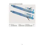
Page 209: ...y absorber shock option NO ERP Code Part No Part Description Qty 1 02 SV1100 02 03 01A SV1100 02 03 01 00A front luxury absorber shock 2 2 02 SV1100 02 03 02A SV1100 02 03 02 00A Rear luxury absorber...

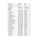
Page 210: ...1 2 19 rod end bearingPOSA12 02 D800 05 01 0002 D800 05 01 00 02 2 20 spacer sleeve 02 D800 05 01 0003 D800 05 01 00 03 8 21 electric cable 02 MV800 06 01 MV800 06 01 00 00 1 22 spotlight 02 D1600 06...

Page 211: ...the second Piston ring 02 DLJ 372 1004033 372 1004033 4 15 oil control steel ring scraper 02 DLJ 372 1004041 372 1004041 8 16 oil control steel ring cushion 02 DLJ 372 1004042 372 1004042 4 17 bearin...

Page 212: ...n pipe3 02 DLJ 472 1014123 472 1014123 1 3 Transmission 1 DOUBLE SCREW ROD 02 DLJ 5T07 1701058A 5T07 1701058A 1 2 shift turning rod 02 DLJ 5T07 1702090A 5T07 1702090A 1 3 SHIFT SELECT SHAFT 02 DLJ 5T0...

Page 213: ...00 1 4 Standard part 1 self locking nut M8 03 02 6177 1 M8 05 6177 1 M8 20 2 self locking nut M6 03 02 6177 1 M6 05 6177 1 M6 20 3 nut M10 1 25 03 02 2842 M10 X 1 25 05 2842 M10 X 1 25 20 4 nut M10 1...

Page 214: ...213 PREPARATION ATTACH INSTRUCTION 1 Remove Packing 1 Remove Packing 2 Unbolt both sides and top of crate carefully remove cut wire ties holding cart lift cart and slide remaining frame out from under...

Page 215: ...00 lower suspension arm FR 1 1 02 D800 02 01 03 D800 02 01 03 00 upper suspension arm FR 1 No Erp code Part name Description Q ty 1 Install the left upper suspension arm F 3 and the left lower suspen...

Page 216: ...3 01 5782 M15X190 05 5782 M15X190 M15 1 5 190 bolt 2 2 02 D800 02 03 0003 D800 02 03 00 03 spacer sleeve shocker 4 1 03 02 6185 1 M15 05 6185 1 M15 M15 1 5 nut 2 No Erp code Part name Description Q ty...

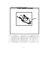
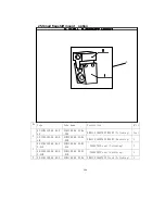
Page 217: ...05 01 00 01 rod end bearing POSA12LH 1 1 02 S650 03 01 04 00A S650 03 01 04 00A right wheel 27 8 12 1 No Erp code Part name Description Q ty 1 Install the shaft of outer tie rod end 2 to left wheel a...

Page 218: ...217 4 Attach tie rod and front wheel...

Page 219: ...6X125 05 5787 M16X125 M16 2 125 bolt 4 2 02 D800 02 02 02A D800 02 02 02 00A rear suspension arm left 1 1 02 SV1100 02 02 01A SV1100 02 02 01 00A rear suspension arm right 1 No Erp code Part name Desc...

Page 220: ...03 02 02 00 drive shaft right 1 1 02 SV800 03 02 01 SV800 03 02 01 00 drive shaft left 1 No Erp code Part name Description Q ty 1 Check the steel cable baffle ring 3 in the groove of the output shaft...

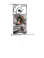
Page 221: ...220 6 Attach drive shaft transmission Steel cable baffle ring 3 1 Caution the Steel cable baffle ring 3 must be confirmed in the groove both sides before attaching drive shaft...

Page 222: ...rber 2 3 03 02 6185 1 M15 05 6185 1 M15 M15 1 5 nut 2 2 02 D800 02 03 0003 D800 02 03 00 03 spacer sleeve shocker 4 1 03 01 5782 M15X80 05 5782 M15X80 M15 1 5 80 30bolt 2 No Erp code Part name Descrip...

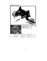
Page 223: ...he hub tighten the nuts 3 2 Attach the left side as above 3 02 S650 03 01 0002 S650 03 01 00 02 wheel nut M12 1 5 8 2 02 S650 03 02 04A S650 03 02 04 00A wheel 27 11 12 BR 1 1 02 S650 03 02 01A S650 0...

Page 224: ...15psi rear tire 15psi check all bolts and nuts are tight 2 start engine make sure oil warning light goes out within 5 10 seconds run engine untile both radiator hoses are warm about 5 minutes 80 degre...

Page 225: ...224 DEALER PRE DELIVERY INSPECTION...

Page 226: ...DITIONAL TERMS AND CONDITIONS OF SALE 1 PROMISE TO PAY By signing this contract Buyer agrees to pay Seller the TOTAL DUE 2 TIME OF ESSENCE Time is of the essence of this contract Sellers acceptance of...

Page 227: ...check In addition Seller will charge Buyer a 25 returned check charge plus any actual charges assessed by Seller s financial institution resulting from such returned check 5 ATTORNEYS FEES If it is ne...

Page 228: ...ents and warrants to Seller that Buyer is over the age of majority and is fully competent to enter into contact Buyer acknowledges that Seller is relying on this representation in e ntering into perfo...

Reviews: