background image

lower than 1.5mm² and the length shall be determined by users according to the field situation) due
to different installation environments;
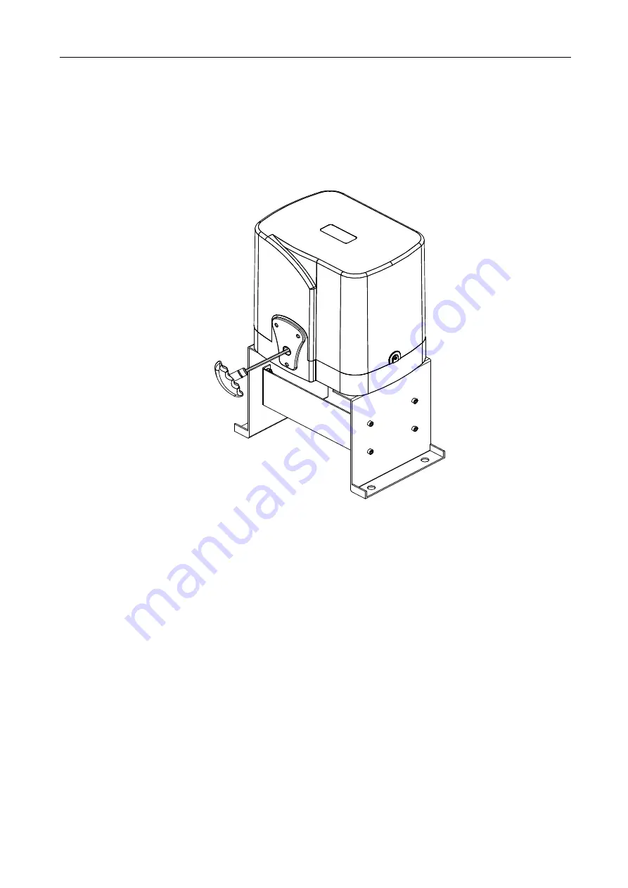
e) Please unlock the main engine before installation, the unlock method is: take out the key cover,
insert the key, and open the manual release bar till it rotates by 90° as shown in Figure 7. Then turn
the output sprocket and the sprocket can be rotated easily;

Rotate

Figure 7

4.3.3 Chain installation

Close the gate; connect the tie rod with chain through chain link; fasten the tie rod to the door

connecting plate by washers and nuts as shown in Figure 8. If necessary, the elasticity of chain can

be adjusted through the tie rod at both ends as shown in Figure 9 and 10. If necessary, the chain

can be shortened. If it need to be lengthened, make sure to use same type of chain.

Summary of Contents for PY1400ACL

Page 1: ...PY1400ACL Sliding Gate Opener User Manual 2017...

Page 2: ...emote control unit is controlled by a single button mode The indicator light on the remote control unit will flicker when the button on it is pressed Main engine and gate can be unlocked by disengagem...

Page 3: ...Picture Name Quantity 1 Main engine 1 2 Manual release bar 1 3 A B C D A B C D Remote control 2 4 Mounting accessories box 1 4 1 Sprocket cover 1 4 2 Chain link 2 4 3 Chain 6m 4 4 Tie rod 2 4 5 Square...

Page 4: ...Vertical mounting plate 2 4 10 Foundation bolt M8 4 4 11 or Magnetic or Spring limit switch block 1 4 12 Inner hexagon screw M6 20 8 4 13 Hexagon screw M6 65 4 Hexagon screw M8 25 4 4 14 Nut M6 20 Nut...

Page 5: ...ton mode Limit switch Spring limit switch Magnetic limit switch Noise 60dB Working duty S2 15min Recording of up remote controls 25 Frequency 433 92 MHz Working temperature 20 C 70 C Package weight 26...

Page 6: ...Figure 1 Gate opener Wireless keypad optional Gate Infrared sensor optional Alarm lamp optional Safety stop block Chain Remote control 4 2 Size of main engine and accessories 4 2 1 Size of main engine...

Page 7: ...and controlling cable with PVC tube and use two PVC tubes to bury motor power cable and controlling cable separately so as to guarantee normal operation of the gate opener and protect the cables from...

Page 8: ...orizontal Horizontal mounting mounting plate plate Nut Nut M6 M6 Spring Spring washer washer 6 Flat Flat washer washer 6 Figure 5 c Assemble the machine engine to the mounting base as shown in Figure...

Page 9: ...as shown in Figure 7 Then turn the output sprocket and the sprocket can be rotated easily Rotate Figure 7 4 3 3 Chain installation Close the gate connect the tie rod with chain through chain link fast...

Page 10: ...shown in Figure 9 Gate Round screw Spring washer 8 Nut M8 Flat washer 8 Tie rod Nut M6 Spring washer 6 Flat washer 6 Figure 9 If door frame is square please use the square screw as shown in Figure 10...

Page 11: ...tallation of chain small and big sprocket as shown in Figure 11 Figure 11 Installation of sprocket cover as shown in Figure 12 Cross Cross screw screw M4 10 M4 10 Sprocket Sprocket cover cover Figure...

Page 12: ...only otherwise the control system will be damaged Earth leakage circuit breaker must be installed where the gate movement can be seen and the minimum mounting height is 1 5m to protect it from being t...

Page 13: ...switch switch block block Chain Chain Hexagon Hexagon screw screw M6 M6 65 65 45 45 Figure 14 Gate Gate Main Main engine engine Chain Chain wheel wheel Chain Chain Spring Spring limit limit switch swi...

Page 14: ...0mm Gate Gate Main Main engine engine chain chain wheel wheel Chain Chain Magnetic Magnetic limit limit switch switch block block Magnet Magnet Spring washer 8 Nut M8 Flat washer 8 Figure 17 Note The...

Page 15: ...ring instruction 1 Connect L and N to the power supply of AC220V 50HZ AC110V 60HZ L is live wire N is Neutral wire and PE is grounding wire 2 Connect LAMP to D1 D2 voltage AC220V 50HZ AC110V 60HZ 3 Co...

Page 16: ...ed ray of the infrared sensor is covered the gate will open immediately to protect user and property security The distance between photocell receiver and photocell emitter should be not less than 2 me...

Page 17: ...rol learning is succeed At most 25 remote controls can be learned Delete remote control Delete remote control that have been learned press the learning button AN1 and LED2 will be on loosen the button...

Page 18: ...Capacitor Lamp Lamp Hall Hall line line Infrared Infrared sensor sensor switch switch Figure 21 Wiring instruction 1 Connect L and N to the power supply of AC220V 50HZ AC110V 60HZ L is live wire N is...

Page 19: ...ipped with microprocessor can be adjusted through potentiometer and dip switch so as to meet different installation requirements 13 13 12 12 SPEED SPEED GND GND VCC VCC OFF OFF ON ON X1 X1 HALL HALL U...

Page 20: ...c close function 5 Meet obstacle reversal function OFF enabled ON disabled Infrared connection Infrared photocell function In the closing process when infrared ray of the infrared sensor is covered th...

Page 21: ...at all remote controls that learned previously have been deleted The fourth button on the remote control is for pedestrian mode press the button the door will open about 1 meter when the door is close...

Page 22: ...move the obstacle 4 Reduce the sensitivity of obstacle 5 Change hall switch parts Remote control doesn t work 1 Battery level of the remote control is low 2 Remote control learning is not completed 1...

Page 23: ...eceiver antenna 1 5 meters above ground The gate moves to the middle position to stop or reverse 1 Motor output force is not enough Intelligent type 2 Sensitivity of obstacle is too big Intelligent ty...

Reviews: