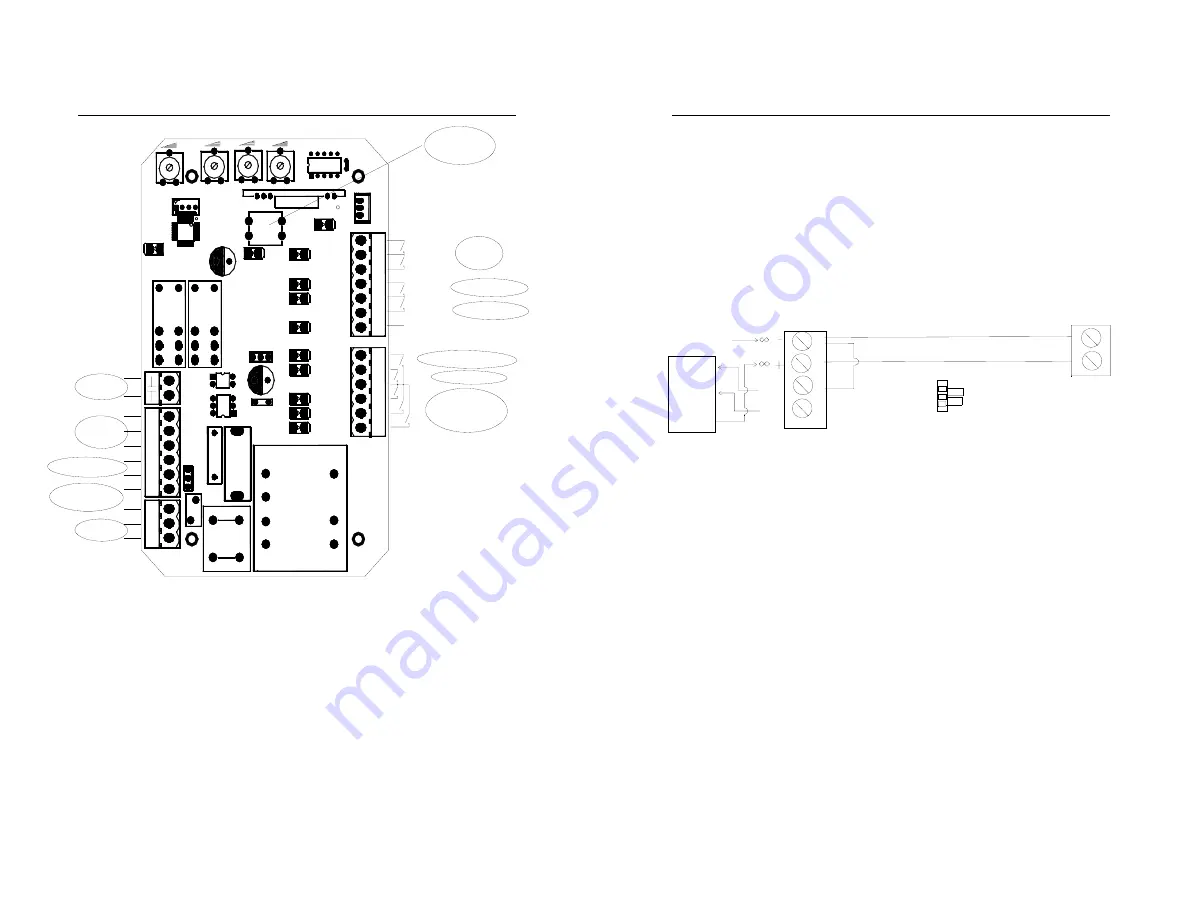
SL600AC SLIDING GATE OPERATOR
10
ON
OFF
N
L
N
SPE
E
D
G
N
D
VC
C
CAP
MOT2
MOT1
COM
MOT
MOT
8
12
11
10
9
7
6
5
4
1
23
PE
LA
M
P
13
PE
L
SW1
T2
9
7
RL
2
RL1
VR2
VR1
6
5
10
1
3
12
2
OC2
OC1
F3
F2
F1
C20
C19
C22
J3
J6
J1
POWER
LEARN
VR4
VR3
S1
U3
U2
VDR1
Q3
J2
HAL
L
U1
J5
X1
J4
POWER
MOTOR
Caution light
Protect Earth
Capacitor
Extral button
switch
O/S/C switch
Pedestrian switch
Infared sensor
Loop detector
Limit
swtich
+12VDC
GND/COM
COM
COM
Learn button
Open limit
Close limit
Fig.8
Wiring notes of control board
a. Power Input (terminal J3): PE (Earth),L (Live),N (Neutral).
SL600AC: AC220V
SL600ACU:AC110V
b. Caution light: connect caution light wire to L and N of
LAMP(terminal J4)
SL600AC: AC220V
SL600AC SLIDING GATE OPERATOR
11
SL600ACU: AC110V
c. Output power supply: 12VDC(7 of J5), COM (9 of J5), I.R. (8 of
J5 is N.C Infrared)
If the infrared beam is interrupted during closing, the gate will reverse
and open immediately. The product is not factory equipped with an
infrared device; the infrared output signal must be N.C.
From four-terminal
to the receiver
COM
OUT
RX Receiver connecting
JUMP
NC OR NO
NC
NO
Form two-terminal to the emitter
12--24V AC/ DC
TX Emitter connecting
power supply
7
9
8
Control board
Terminal J5
Fig.9 infrared
Schematic diagram
d. Three-button switch / single-button switch (keypad): The
SL600AC is equipped with interfaces for three-button switch and
single-button switch (keypad).
To install the keypad attach one lead of your keypad to ‘5’ of
terminal J2 and the other to the ‘4(COM)’. The keypad will
function in single channel mode.
For three-button switch installation, use the terminals for
multi-channel mode. Connect open wire of external button switch
to ‘1 (OPEN)’ of terminal J2, connect close wire of switch to ‘2
(CLOSE)’, connect stop wire of switch to ‘3(STOP)’, connect
common wire of switch to ‘4(COM)’.


