MacGregor Industries
45 AERO
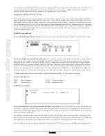
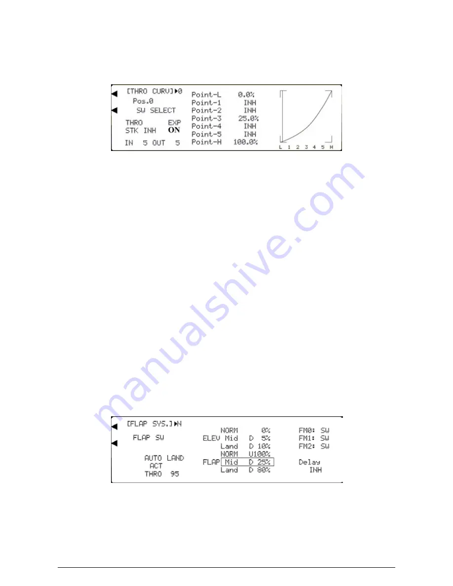
To set a Throttle curve point,
highlight the required point by rotating the Scroll Bar and click on it to bring up the sub
menu. The highlighting is surrounded by a box to indicate that it is selected. Rotate the Scroll Bar to alter the setting.
When the required setting is achieved, click the Scroll Bar to exit the sub menu. For mix points 0, 3 and 6, to return the
figures to the default of zero, press the clear (CLR) key at the left hand side of the screen. For mix points 1, 2, 4 and 5, the
clear key (CLR) at the left side of the screen returns the mix point to inhibited (INH). Notice that the displayed graph
changes to reflect the figures entered.
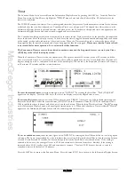
Note that an inhibited mix point plays no part in the mixing procedure. The default mix therefore, has only three active
points. This is most noticeable when using the exponential (EXP) feature to smooth the curve. To activate the inhibited
mix points, click on them twice (once to activate and once to exit). The "hidden" value will appear and the mix point will
become active.
Press the LIST key to return to the Function Menu. Press the enter (ENT) key to return to the Information Display Screen.
Flap System
Please note that the FLAP SYS. menu choice will only appear if SYS. has been activated for the Flap channel
output in System Mode - DeviceSEL.
The Function Menu List is accessed from the Information Display Screen by pressing the LIST key. From the Function
Menu List, rotate the Scroll Bar to highlight the "FLAP SYS." menu choice and click the Scroll Bar.
•
Three switch controlled Flap positions.
•
Elevator compensation for each Flap position.
•
Throttle override for aborted landings.
•
Programmable Flap deployment delay.
•
Flight Mode controlled Flap deployment.
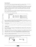
The "NORM", "Mid" and "Land" adjacent to "FLAP" and "ELEV" refer to the three positions of the Flap switch with
NORM corresponding to the top position, Mid corresponding to the mid position and Land corresponding to bottom
position. A Flap/Elevator position between U 125% (up 125%) and D 125% (down 125%) may be set for each switch
position.
For information, the figure to the right of [FLAP SYS.] on the top left of the screen changes as the Flap activation switch is
moved. The N, M and L correspond to the three Flap switch positions NORM, Mid and Land as above.
Please note that the Flight Mode switch choices FM0:, FM1: and FM2: will only appear if Flight Modes have been
activated in System Mode - DeviceSEL.
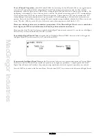
To set a Flap deflection value,
highlight the required switch position adjacent to "FLAP" at the bottom of the screen by
rotating the Scroll Bar and click on it to bring up the sub menu. The figure is surrounded by a box to indicate that it is
selected. Rotate the Scroll Bar to adjust the value. To return the figures to the default of 0%, press the clear (CLR) key at
the left hand side of the screen. When the required setting is achieved, click the Scroll Bar to exit the sub menu.
Summary of Contents for PCM9XII
Page 1: ...MacGregor Industries MACGREGOR INDUSTRIES Instruction Manual PCM9XII ...
Page 4: ...MacGregor Industries This page is intentionally blank ...
Page 43: ...MacGregor Industries 39 HELI ...
Page 65: ...MacGregor Industries 61 AERO ...
Page 85: ...MacGregor Industries 81 GLIDER ...
Page 86: ...MacGregor Industries This page is intentionally blank ...
Page 87: ...MacGregor Industries This page is intentionally blank ...


