MacGregor Industries
59 AERO
Servo Monitor
The Function Menu List is accessed from the Information Display Screen by pressing the LIST key. From the Function
Menu List, rotate the Scroll Bar to highlight the "MONITOR" menu choice and click the Scroll Bar.
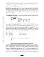
The Servo Monitor displays each channel and shows the corresponding movement of each channel as the associated stick,
lever or Digital Trim is moved. To aid identification, channels are named according to their assignment in System Mode -
DeviceSEL. As an example, with a single Aileron channel, the Aileron channel is identified as AILE. When a second
Aileron channel (GEAR say) is also assigned to Aileron, the monitor changes the Aileron identification to RAIL (right
Aileron) and the GEAR identification to LAIL (left Aileron). In general, left channels are prefixed with L and right
channels are prefixed with R.
The centre of the bar represent zero travel (or neutral). The markers on the bar represent 50%, 100% and 150% servo
travel for each side of neutral with the extreme ends representing 150%. Please note that the marker movement direction is
arbitrary as it depends on the Servo Reverse settings.
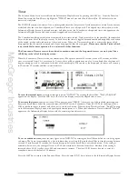
A second monitor screen shows all Digital Trim settings.
To swap the display between the Servo Monitor and Digital Trim display,
select the display indicator (MONI or
TRIM), at the top left of the screen and click on it to toggle between them. The display indicator changes between MONI
for the Servo Monitor screen and TRIM for the Digital Trim display.
When Flight Modes are active and the trim settings are assigned to each Flight Mode, the TRIM list shows the trim settings
for each Flight Mode.
Press the LIST key to return to the Function Menu. Press the enter (ENT) key to return to the Information Display Screen.
Throttle Cut
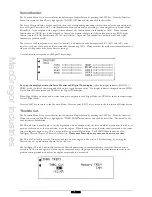
The Function Menu List is accessed from the Information Display Screen by pressing the LIST key. From the Function
Menu List, rotate the Scroll Bar to highlight the "THRO TRIM" menu choice and click the Scroll Bar. The default is for
both systems to be inhibited.
The Throttle trim is usually used to cut the engine and with an analogue trim, the lever would be moved from the tick-over
position at the centre, to the low position, to cut the engine. When the engine stops, the trim can be returned to the centre
ready for the next engine start. This is not possible with normal Digital trims. The PCM9XII has the choice of an
Intelligent Throttle Trim or a Throttle Cut function.
Please note that only one system can be active at a time.
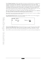
The Throttle Cut facility uses the Trainer switch into stop the engine (while at a low Throttle setting), by moving the
Throttle servo to a predetermined point below tick-over.
The Intelligent Throttle Trim facility enables the Throttle trim setting to be remembered so that if the Throttle trim is
moved to full low in one operation (as an engine cut procedure), a single upward click of the trim returns the trim to the
position existing immediately before the engine cut procedure was enacted.
Summary of Contents for PCM9XII
Page 1: ...MacGregor Industries MACGREGOR INDUSTRIES Instruction Manual PCM9XII ...
Page 4: ...MacGregor Industries This page is intentionally blank ...
Page 43: ...MacGregor Industries 39 HELI ...
Page 65: ...MacGregor Industries 61 AERO ...
Page 85: ...MacGregor Industries 81 GLIDER ...
Page 86: ...MacGregor Industries This page is intentionally blank ...
Page 87: ...MacGregor Industries This page is intentionally blank ...


