MacGregor Industries
68 GLIDER
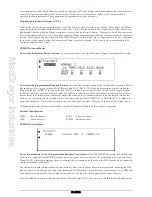
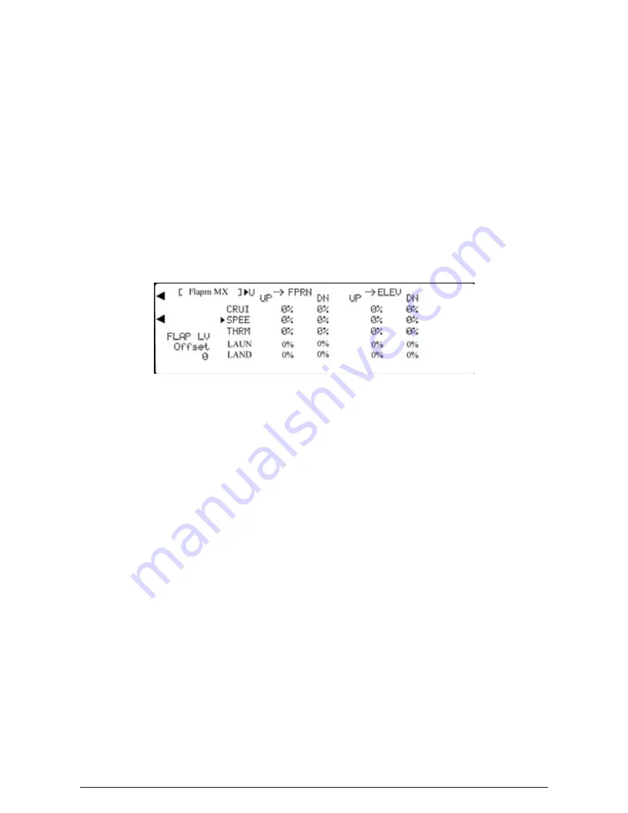
The Flaperon mix enables the Ailerons to additionally act as Flaps to increase the Flap authority and effectively have full
length Flaps. This can improve the performance when using a slight reflex Flap (wing trailing edge raised) for speed or a
slight camber Flap (wing trailing edge lowered) for thermal soaring. At the same time, the tendency to tip stall can be
reduced by having less Aileron than Flap movement (wing tip wash out).
Different values of Aileron to Flap mix may be set for each of the five Flight Modes. Values between
±
125% may be
entered although only values between 0% and +100% would normally be used. With 0% mix (mix inhibited), the Ailerons
do not move as Flaps, while with +100% mix, the Ailerons and Flaps move the same amount and in the same direction. A
negative mix causes the Ailerons and Flaps to move in opposite directions. Separate, different, values of mix for Flap up
and Flap down can be set if required. To prevent any tendency for the model to balloon when the Flaps are lowered, or
sink when the Flaps are raised, for each Flap to Aileron mix, a compensating Elevator movement may be programmed.
A Flap lever offset value between
±
200 may be programmed to re-define the neutral of the Flap lever (like a mix sub trim).
Any offset is included in the Aileron movement of the Flaperon mix. A value of 200 corresponds to about 125% of the
available Flap movement. Note that the Flap travel is a combination of that specified in the TRVL ADJ. (Travel Adjust)
and FLAP RATE (Flap rate) sections.
For information only, a marker arrow on the screen points to the current Flight Mode switch selection. In addition, the
character to the right of the [Flaprn MX] on the top left of the screen displays "U" when the Flap lever is in the up position
and "D" when the Flap lever is in the down position.
Please note that the display will only show the Flight Modes activated in System Mode – DeviceSEL.
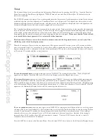
To set a Flaperon mix value,
highlight the required figure by rotating the Scroll Bar and click on it to bring up the sub
menu. The figure is surrounded by a box to indicate that it is selected. Rotate the Scroll Bar to alter the setting. To return
the figures to the default of 0, press the clear (CLR) key at the left hand side of the screen. When the required setting is
achieved, click the Scroll Bar to exit the sub menu.
To set a Flap lever offset value,
highlight "Offset" by rotating the Scroll Bar and click on it to bring up the sub menu.
The figure is surrounded by a box to indicate that it is selected. Rotate the Scroll Bar to alter the setting. To return the
figures to the default of 0, press the clear (CLR) key at the left hand side of the screen. When the required setting is
achieved, click the Scroll Bar to exit the sub menu.
Press the LIST key to return to the Function Menu. Press the enter (ENT) key to return to the Information Display Screen.
Aileron to Rudder Mix
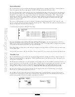
The Function Menu List is accessed from the Information Display Screen by pressing the LIST key. From the Function
Menu List, rotate the Scroll Bar to highlight the "AIL->RUD" M menu choice and click the Scroll Bar.
When turning a model using the Ailerons, a more aerodynamically balanced turn is achieved if both Aileron and Rudder are
used to control the turn. By using the Aileron to Rudder mix, the control coupling can be activated automatically.
The Aileron to Rudder coupling may be set for each of the five Flight Modes with different left or right figures. Values
between
±
125% may be entered although only those between 0% and +100% would normally be used. With 0%, the
coupling is inhibited and with +100%, the Ailerons and Rudder move the same amount. Negative figures reverse the
direction of the Rudder movement.
For information only, a marker arrow on the screen points to the current Flight Mode switch selection. In addition, the
character to the right of the [AIL->RUD M] on the top left of the screen displays "R" when the Aileron stick is moved to
the right of neutral and "L" when the stick is moved to the left.
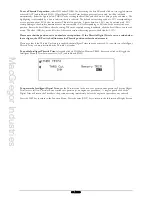
To set a mix value,
highlight the required figure by rotating the Scroll Bar and click on it to bring up the sub menu. The
figure is surrounded by a box to indicate that it is selected. Rotate the Scroll Bar to alter the setting. To return the figures to
Summary of Contents for PCM9XII
Page 1: ...MacGregor Industries MACGREGOR INDUSTRIES Instruction Manual PCM9XII ...
Page 4: ...MacGregor Industries This page is intentionally blank ...
Page 43: ...MacGregor Industries 39 HELI ...
Page 65: ...MacGregor Industries 61 AERO ...
Page 85: ...MacGregor Industries 81 GLIDER ...
Page 86: ...MacGregor Industries This page is intentionally blank ...
Page 87: ...MacGregor Industries This page is intentionally blank ...


