17
2-5
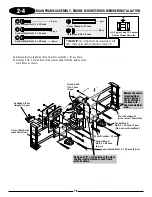
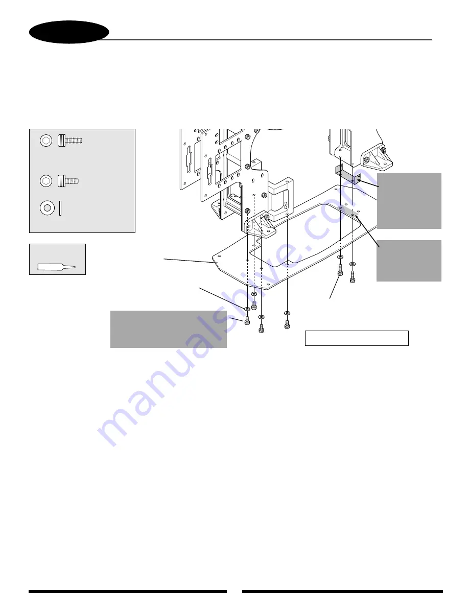
MAIN FRAME ASSEMBLY: BOTTOM PLATE INSTALLATION
Socket Head Bolt, 3 x 8 mm
(included with the
grounding plate)
*
Socket Head Bolt, 3 x 10 mm (2 pcs)
(included in kit)
..............2 pcs
................4 pcs
..........................6 pcs
Socket Head Bolt, 3 x 6 mm
Socket Head Bolt, 3 x 6 mm (4 pcs)
Replace the 3 x 6 mm bolts with
the 3 x 8 mm bolts included with
the RF grounding plate.
Flat Washer, 3 mm
Flat Washer, 3 mm (6 pcs)
Carbon Fiber
Bottom Plate
*
*
*
*
Use Red
Threadlock
*
Tighten bolts at this time.
A) Remove a
3
/
4
" x 1
1
/
4
" portion of the clear coating from the top of the bottom carbon fiber plate as shown.
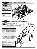
B) Insert the brass RF grounding plate between the cross member “B” and the inside of the two main frames as shown.
C) When installing the carbon bottom plate, replace the four 3 x 6 mm socket head bolts that connect the carbon plate to
the motor mount with the four 3 x 8 mm socket head bolts included with the RF grounding plate.
Insert the brass RF
grounding plate so
it’s positioned
between the cross
member “B” and
the two main
plates.
Remove a
3
/
4
" x
1
3
/
4
" portion of
the clear coating
from plate as
shown.
3/4"
1-1/4"
When properly installed, the RF grounding plate will make contact with both the two main frames and the bottom
carbon plate in the areas where the clear coating has been removed. This will properly complete the ground between
the main frame and the bottom carbon plate.
Summary of Contents for Vigor CS
Page 64: ...64 E A C D G F DECAL PLACEMENT ...
Page 65: ...65 B 3 2 5 1 DECAL PLACEMENT ...

