23
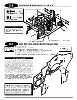
3-7
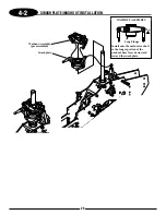
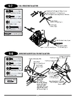
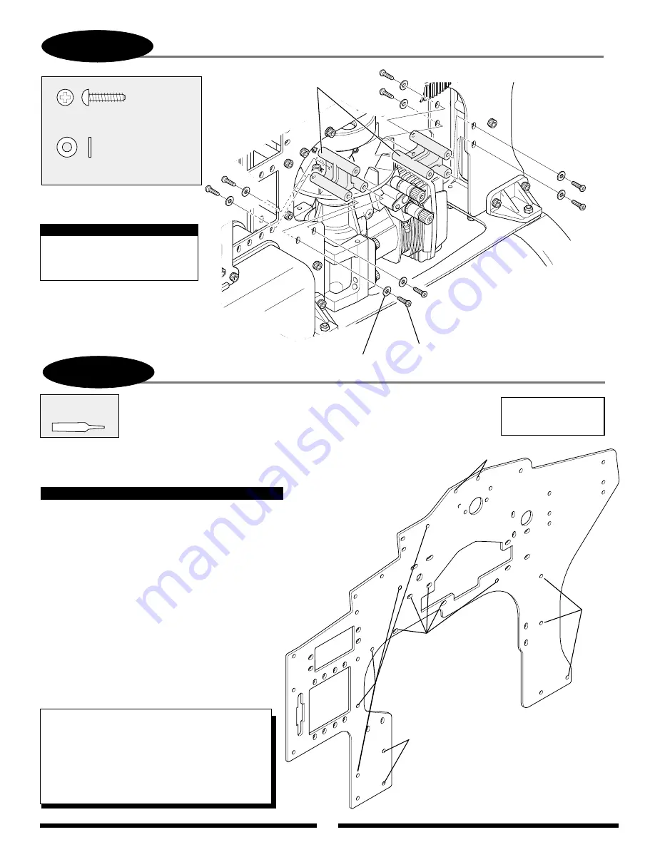
COOLING FAN SHROUD BRACKET ATTACHMENT
Self Tapping Screw, 3 x 12 mm
Self Tapping Screw, 3 x 12 mm (8 pcs)
Cooling Fan Shroud Brackets (2 pcs)
Flat Washer, 3 mm
Flat Washer, 3 mm (8 pcs)
.............8 pcs
.........................8 pcs
3-8
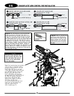
BOLT TIGHTENING ORDER/GEAR MESH ADJUSTMENT
Bolt Tightening Order:
1. Motor Mount to Main Frame Plates
2. Start Shaft Bearing Block/Bearing Blocks “A” & “B”
3. Crossmember “A”, and front Crossmember “B” to Main Frame Plates
4. Upper Main Shaft Bearing Block to Main Frame Plates
5. Rear Crossmember “B” to Main Frame Plates
6. Tighten all remaining bolts on frame left loose from Steps 2-1, 2-2, and 2-4
2
5
4
*
*
*
Do not tighten screws at this
time. They will be tightened in
Step 3-9.
Note:
6
Tighten all
remaining bolts.
Use Red
Threadlock
Once the engine has been installed, adjust the gear mesh of
the main pinion so that a slight amount of “backlash” is
achieved. One method for achieving the proper clearance is to
insert a folded piece of paper between the two gears, press the
gears together, then secure the bearing blocks in place. When
setting the gear mesh, make sure that the pinion gear remains
parallel to the main drive gear teeth, as it is possible to alter the
pinion gear angle during adjustment.
If you find difficulty achieving proper alignment of the
pinion, it is also possible to loosen the six bolts that attach the
engine mount to the main frame. This will allow the engine/
mount to be repositioned to achieve the proper gear mesh.
Once the desired gear mesh has been achieved, tighten all
loose bolts from Step 2-1. Please remember to use thread-lock
on the bolts securing the upper start shaft pinion block.
Please also remember to apply threadlock and tighten the
two 3 x 14 mm socket head bolts that connect bearing block
“A” to bearing block “B” . (see Step 1-1 for details).
Gear Mesh Adjustment
1
3
TEAM TIP:
Once the gear mesh/engine alignment
has been established, rotate the start shaft assembly
first counterclockwise, then clockwise. When moved
clockwise, the start shaft assembly should move
freely with little or no resistance. If resistance is
present, the clutch/start shaft assembly are not
aligned properly. Readjust as necessary.
Summary of Contents for Vigor CS
Page 64: ...64 E A C D G F DECAL PLACEMENT ...
Page 65: ...65 B 3 2 5 1 DECAL PLACEMENT ...

