24
3-9
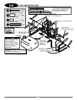
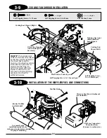
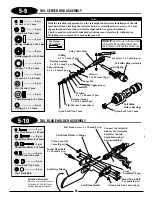
COOLING FAN SHROUD INSTALLATION
3-10
INSTALLATION OF THE MUFFLER/FUEL LINE CONNECTIONS
Self Tapping Screw, 3 x 12 mm
Pressure Fuel Line Attachment
(not included)
Fuel Line Connection
Main Fuel Line
(Connect to carburetor.)
Muffler Bolts
.60-Size Muffler
(not included)
...4 pcs
........6 pcs
................4 pcs
Self Tapping Screw, 2.6 x 8 mm
Flat Washer, 3 mm
Self Tapping Screw, 3 x 12 mm (4 pcs)
Cooling Fan Shroud (Right)
Self Tapping Screw,
2.6 x 8 mm (6 pcs)
Flat Washer, 3 mm (4 pcs)
Cooling Fan
Shroud (left)
Glow Plug Opening
(can be enlarged if
necessary)
Tighten after right
shroud half has
been aligned.
TEAM TIP:
The best alignment
of the fan shroud can be achieved
by attaching only the right half of
the shroud. Next, align the
mounts so the shroud is centered
around the fan. Tighten the fan
mounts then attach the left
half of the shroud. With some
engines and Ni-starters, you
may need to trim the glow plug
opening in the shroud for
additional clearance.
For muscle pipe
installation, please refer
to the muscle pipe instructions
for proper mounting.
Summary of Contents for Vigor CS
Page 64: ...64 E A C D G F DECAL PLACEMENT ...
Page 65: ...65 B 3 2 5 1 DECAL PLACEMENT ...

