31
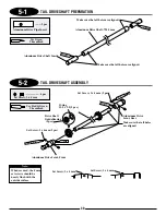
..................... 4 pcs
........................1 pc
Set Screw, 4 x 6 mm
Washer, 5 x 9 x 1 mm
Washer, 5 x 9 x 1 mm
Use Green
Threadlock
Gree
n
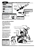
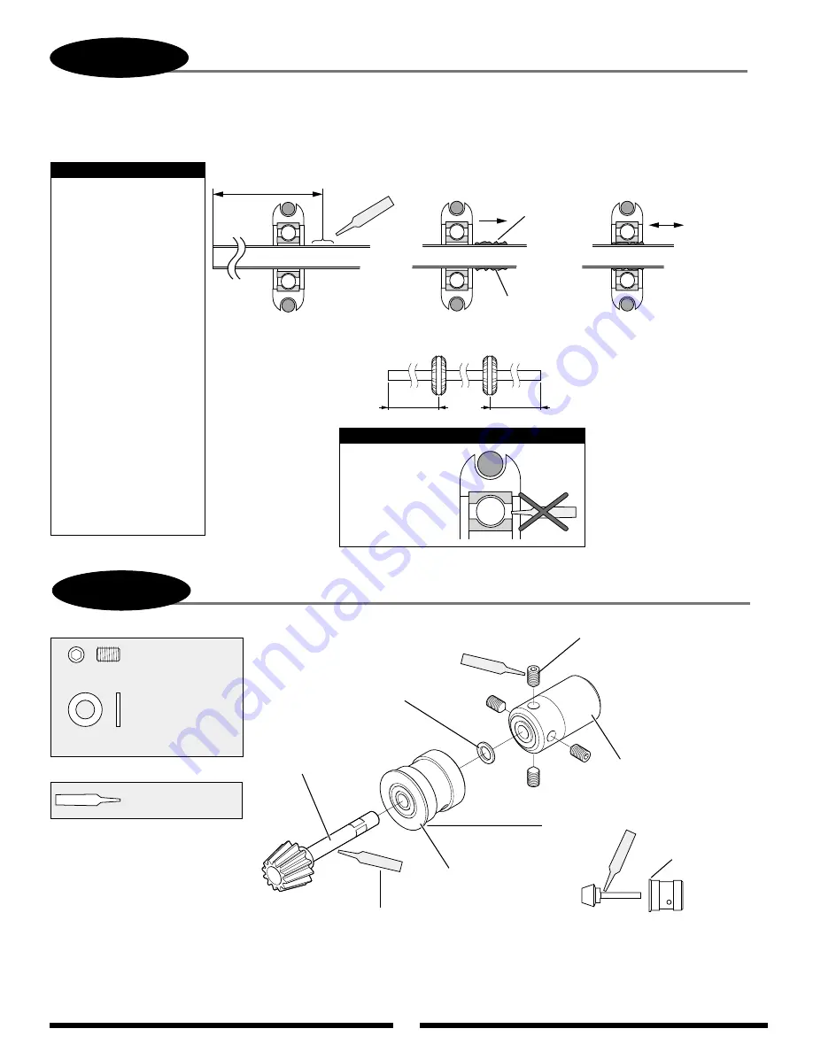
Set Screw, 4 x 6 mm (4 pcs)
Tail Drive Joint, Front
Bevel Pinion
Bearing Case
Bevel Pinion Gear
Flange
Bevel Pinion Bearing Case Direction
Gree
n
Flange must face bevel gear.
Gree
n
Apply a thin coating of green threadlock
to shaft pinion of assembly.
Poly Zap
Slide and spread.
Poly Zap
260 mm/230 mm
Poly Zap
Wipe lightly
w/finger or towel.
Step A
Step B
Step C
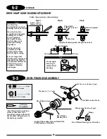
DRIVE SHAFT GUIDE BEARING ATTACHMENT
Attach the tail drive joint and
secure so that there is no
fore/aft movement of the shaft,
but the shaft will spin freely in
the bearing assembly.
5-3
BEVEL PINION GEAR ASSEMBLY
Note:
Use Poly Zap
(not included) to attach
bearings to the drive shaft.
Once the Poly Zap
is applied and the guide
bearings are in their
correct positions
(260 mm/230 mm),
the Poly Zap can be
quick cured using
Zip Kicker.
Position the shaft
assembly on a flat
surface before/while
the Poly Zap is curing.
It is very important
that the guide bearings be
attached to the shaft at
non equal measurements
as shown to prevent
resonance vibration
and fatigue.
Lightly oil bearings after the glue has dried.
Do not apply
Poly Zap to
inside of ball
bearings.
Note:
260 mm
230 mm
Follow this procedure when attaching:
Front
Rear
Bearing Positions
5-2
continued
Summary of Contents for Vigor CS
Page 64: ...64 E A C D G F DECAL PLACEMENT ...
Page 65: ...65 B 3 2 5 1 DECAL PLACEMENT ...


