50
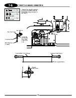
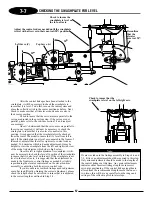
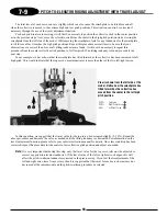
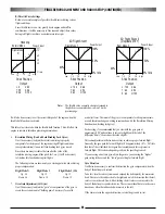
7-1
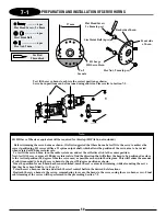
PREPARATION AND INSTALLATION OF SERVO HORNS
............. 6 pcs
................. 6 pcs
..................... 6 pcs
Flat Head Screw, 2 x 8 mm
Steel Joint Ball
Hex Nut, 2 mm
Cut*
See note
JR Large
HD Servo Horn
27 mm
Front side
of horn
Back side of horn
Flat Head Screw
2 x 8 mm(6 pcs)
Steel Joint Ball (6 pcs)
Hex Nut, 2 mm (6 pcs)
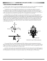
Test fit the servo horns to achieve the correct position as shown.
Servo horn positions can be fine tuned using sub trim. Please refer to Section 7-2.
Red
Use Red
Threadlock
JR HD Servo Wheels or equivalent will be required for this step (JRPA216, not included)
Before trimming the servo horns as shown, it is first suggested that these horns be test fit to the servo to achieve the
correct positioning. JR servos utilize a 21 spline output shaft, which allows the position of the servo arm to be varied
when rotated at 180-degree intervals.
To test fit the servo horns, turn the radio system on, and set the collective stick to the center position.
Next, test fit the servo arms at 180-degree intervals to find the direction that will allow the horn to be positioned as close
to the vertical position (90 degrees from the servo case) as possible as shown in the diagram. This will reduce the amount
of sub trim needed to bring the servo horns to the exact 90-degree position as shown.
Once the position for each horn has been established, mark the servo arms for trimming, while also noting the servo
that they have been fitted to (A, B, or C).
Trim the servo horns as shown and attach the steel control balls in the desired hole locations.
Reattach the servo horns to the servos, remembering to secure the horns to the servos using the servo horn screw. Final
sub trimming of the servos will be performed in the proceeding Section 7-2.
Note:
Summary of Contents for Vigor CS
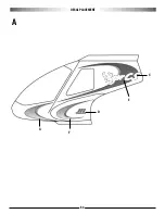
Page 64: ...64 E A C D G F DECAL PLACEMENT ...
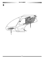
Page 65: ...65 B 3 2 5 1 DECAL PLACEMENT ...

