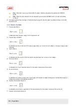
2.3.5 Ship Speed
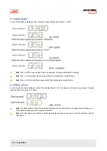
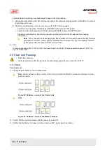
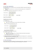
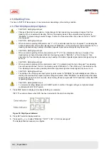
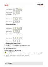
Current Ship Speed is displayed. See example: Present Speed input system is "GPS".
Note When a GPS communication failure is generated, the data indicator starts blinking.
Note When a LOG (contact) failure is generated, the data indicator starts blinking.
Note When a LOG (serial) failure is generated, the data indicator starts blinking.
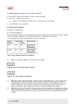
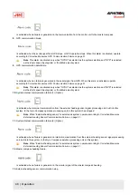
2.3.6 Rate of Turn
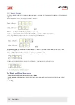
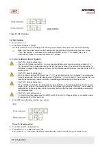
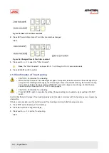
Current ship's turn rate is displayed. Unit of the indicated Rate of Turn is in degrees / minutes. See example: Presently
right turn with 30 degrees / 0 minutes.
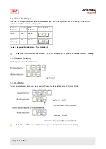
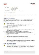
Note The Data indicator shows bar indication (blinking) until the master Gyro Compass starts to follow up, or
when "External heading sensor" system is selected.
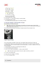
Note When the ship makes a left turn, the Mode indicator shows a minus sign (-), which is indicated in the far
right space.
35 | Operation
Summary of Contents for Alpatron AlphaMidiCourse
Page 1: ...AlphaMidiCourse Gyro Compass Installation and Operation Manual www jrc am ...
Page 68: ...5 1 1 Outline Control Unit One Gyro Compass System Figure 41 Control Box 68 Appendices ...
Page 69: ...5 1 2 Operating Panel Figure 42 Operating Panel 69 Appendices ...
Page 70: ...5 1 3 Master Compass Figure 43 Main Unit 70 Appendices ...
Page 71: ...Figure 44 Open Gyro Compass 71 Appendices ...
Page 73: ...5 1 5 Connection Diagram Figure 46 Connection Diagram 73 Appendices ...
Page 74: ...5 1 6 Cable Diagram Figure 47 Cable Diagram 74 Appendices ...
Page 75: ...5 1 7 Installation Drawing Figure 48 Installation Drawing 75 Appendices ...
Page 76: ...5 1 8 Terminal Board Figure 49 Terminal Board 76 Appendices ...

