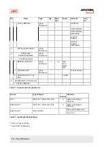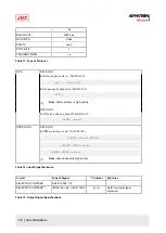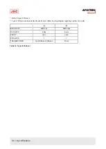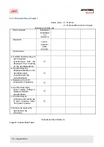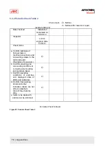
Note Refer to the As Built plan kept on board of the ship for the connected equipment.
2. Operate it according to the particular Operator Manual of the equipment, when a failure has been activated.
3. Contact Alphatron Marine Service Engineer, or agent, after checking steps 1 and 2.
4.6.5.15 Gyro Compass does not Function, when Power Switch on the Operating Panel turned ON.
•
WARNING - Power Supply Failure (alarm code 1)
•
Pay full attention to avoid electric shock when checking the power supply.
•
When checking fuses, turn "OFF" the power switch on the operating panel and further disconnect the power
cable from the ship’s distribution board before checking fuses.
1. Confirm there is power on the power supply cable and the emergency power supply.
INFO: To confirm this, execute as in Power Supply Failure (alarm code 1) on page 60.
2. Check fuses if there is no problem with the power supply.
Note First disconnect the main/emergency power supply.
INFO: One Gyro Compass system
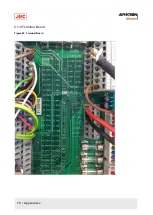
Fuse F6 (Main Supply) and F9 (Emergency Supply, see Table 19: Fuse Replacement on page 65) are located in
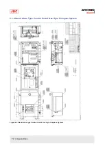
the upper side of the ITERM terminal board of the control unit, see Figure 45: Stand alone type Control Unit of One
Gyro Compass System on page 72 and Figure 49: Terminal Board on page 76
3. Contact Alphatron Marine Service Engineer, or agent, immediately after checking steps 1 and 2.
4.6.5.16 Alarm is Activated at the Same Time when Power Switch Turned ON
1. Turn OFF the power switch, when error code "3" and "A" are activated at the same time
2. Turn back ON after approx. 1 minute.
3. Check the fuse of the inverter, if the status does not change after step 1.
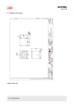
Note The fuse (F1 - 12A) is situated in the base of the master compass, see Master Compass on page
70.
4.6.5.17 Others
When failures and alarms, other than those mentioned before, are activated and when the replaced fuse has blown
again, take following actions:
1. Turn OFF the power switch on the operating panel.
2. Disconnect the power supply from the ship’s distribution board, etc.
3. Contact Alphatron Marine Service Engineer, or agent, immediately.
Note In such event, prompt service action is available when the alarm code is advised.
4.6.5.18 When Failures cannot be fixed On Board
Refer Information to be supplied to Alphatron Marine on page 80 when failures cannot be fixed on board.
64 | Maintenance
Summary of Contents for Alpatron AlphaMidiCourse
Page 1: ...AlphaMidiCourse Gyro Compass Installation and Operation Manual www jrc am ...
Page 68: ...5 1 1 Outline Control Unit One Gyro Compass System Figure 41 Control Box 68 Appendices ...
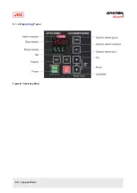
Page 69: ...5 1 2 Operating Panel Figure 42 Operating Panel 69 Appendices ...
Page 70: ...5 1 3 Master Compass Figure 43 Main Unit 70 Appendices ...
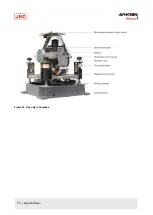
Page 71: ...Figure 44 Open Gyro Compass 71 Appendices ...
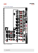
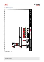
Page 73: ...5 1 5 Connection Diagram Figure 46 Connection Diagram 73 Appendices ...
Page 74: ...5 1 6 Cable Diagram Figure 47 Cable Diagram 74 Appendices ...
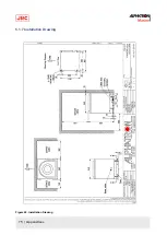
Page 75: ...5 1 7 Installation Drawing Figure 48 Installation Drawing 75 Appendices ...
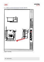
Page 76: ...5 1 8 Terminal Board Figure 49 Terminal Board 76 Appendices ...

