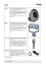
Repeater
Compass
The repeater compass receives the ship’s heading
bearing signal transmitted from the master compass
and remotely indicates the bearing.
The repeater (weight: 5 kg) has an analogue display
for the indication of the heading display. The case is
made of GRP (Glass fiber Reinforced Plastic, thus
corrosion free) and has a waterproof construction, able
to use on open deck.
The repeater (ø246,3 mm) will be delivered with 1.8
meter cable.
Repeater
Holder
The repeater compass mounting bracket has a gimbal
ring to support the repeater compass horizontally when
the ship is rolling and pitching. The repeater compass
is supported with the pins in the gimbal ring.
A junction box, fixed on the bracket, consists of a
switch, a dimmer for illumination and terminal boards
to connect the signal cable from the master compass
and the cable to the repeater compass.
The bracket weighs 8 kg and has a diameter of 354
mm.
Repeater Stand The repeater stand (height: 1330 mm, weight: 25 kg)
can be used when a repeater compass is installed on
the deck.
It has a gimbal ring at the upper part of the stand to
support the repeater compass horizontally, even when
the wipe is rolling and pitching. The stand body is
made of GRP (Glass fiber Reinforced Plastic, thus
corrosion free) and has a waterproof construction, able
to use on open deck. At the middle part of the stand,
there is a switch for dimmer and illumination.
Azimuth Circle
& Storage Box
The azimuth circle is placed on the bezel ring of
the repeater compass to support the repeater
compass horizontally with two levels. In this condition,
astronomical observation can be made with the
mirror and the slit located on the azimuth circle, and
measurements of objects with the lubber’s line and the
slit. Weight 2.2 kg,
∅260,5
mm.
Table 21: Accessories
81 | Appendices
Summary of Contents for Alpatron AlphaMidiCourse
Page 1: ...AlphaMidiCourse Gyro Compass Installation and Operation Manual www jrc am ...
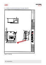
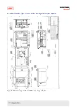
Page 68: ...5 1 1 Outline Control Unit One Gyro Compass System Figure 41 Control Box 68 Appendices ...
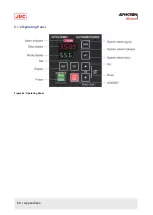
Page 69: ...5 1 2 Operating Panel Figure 42 Operating Panel 69 Appendices ...
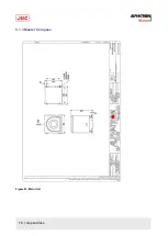
Page 70: ...5 1 3 Master Compass Figure 43 Main Unit 70 Appendices ...
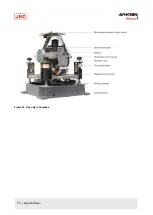
Page 71: ...Figure 44 Open Gyro Compass 71 Appendices ...
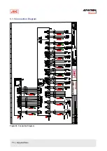
Page 73: ...5 1 5 Connection Diagram Figure 46 Connection Diagram 73 Appendices ...
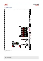
Page 74: ...5 1 6 Cable Diagram Figure 47 Cable Diagram 74 Appendices ...
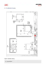
Page 75: ...5 1 7 Installation Drawing Figure 48 Installation Drawing 75 Appendices ...
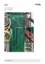
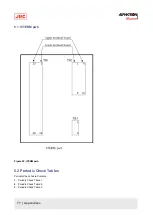
Page 76: ...5 1 8 Terminal Board Figure 49 Terminal Board 76 Appendices ...

