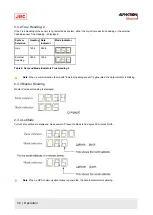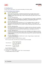
2.3.7 Alarm Content
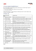
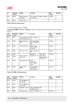
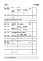
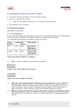
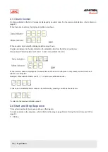
An alarm activated in the Gyro Compass is displayed by an alarm code. For the alarm code indication, refer to Alarm on
page 47.
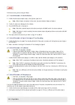
When there are no alarms, the display indication is as shown:
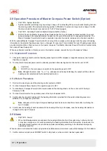
When an alarm is activated the display indication is as shown.
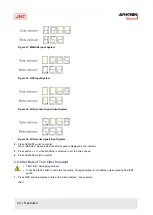
Alarms are displayed in the data indicator in the activated order from the left as shown below.
See example: Presently alarms with code 1, 2 and 3 were activated in order.
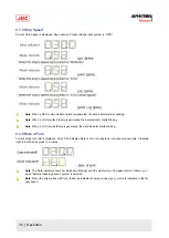
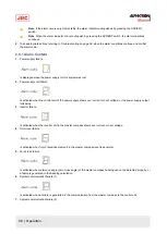
When 4 alarm codes are displayed at the same time and the dot in fourth place is not present, means more than 5
alarms were activated.
Example: When alarms of alarm code 1, 2, 3, c and d were activated in order.
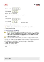
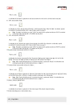
In this case, not-indicated alarm code can be confirmed by pressing
▲
switch as shown below.
To return to the previous indication, press
▼.
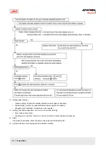
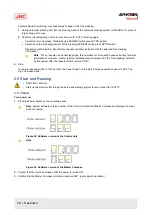
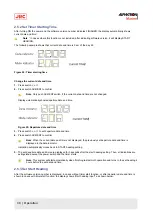
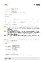
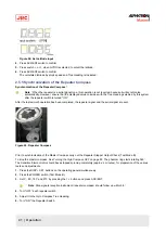
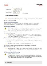
2.4 Start and Stop Sequence
This system operates in the sequence shown in the diagram
For each operation in the sequence, refer to Start and Running on page 38 and Turning the Gyro Compass OFF on
page 52.
1. Starting
36 | Operation
Summary of Contents for Alpatron AlphaMidiCourse
Page 1: ...AlphaMidiCourse Gyro Compass Installation and Operation Manual www jrc am ...
Page 68: ...5 1 1 Outline Control Unit One Gyro Compass System Figure 41 Control Box 68 Appendices ...
Page 69: ...5 1 2 Operating Panel Figure 42 Operating Panel 69 Appendices ...
Page 70: ...5 1 3 Master Compass Figure 43 Main Unit 70 Appendices ...
Page 71: ...Figure 44 Open Gyro Compass 71 Appendices ...
Page 73: ...5 1 5 Connection Diagram Figure 46 Connection Diagram 73 Appendices ...
Page 74: ...5 1 6 Cable Diagram Figure 47 Cable Diagram 74 Appendices ...
Page 75: ...5 1 7 Installation Drawing Figure 48 Installation Drawing 75 Appendices ...
Page 76: ...5 1 8 Terminal Board Figure 49 Terminal Board 76 Appendices ...


