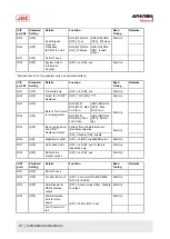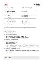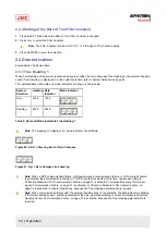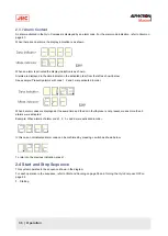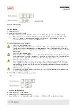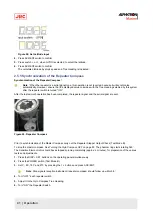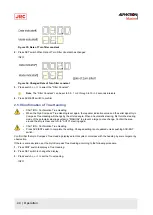
Figure 28: Set Latitude Input
4. Press ACK/ENT switch to confirm.
5. Press switch
▲,
or
▼,
when GYRO is selected, to select the latitude.
6. Press ACK/ENT switch to confirm.
The calculated latitude by ship's speed and True Heading is indicated.
2.5.5 Synchronization of the Repeater Compass
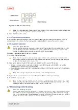
Synchronization of the Repeater Compass¹.
Note ¹When the repeater is a serial signal type, this operation is not required, because it will synchronize
automatically. However, ensure that the displayed value coincides with the True Heading selected by this system
after the repeater switch is turned "ON".
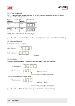
After the last azimuth operation has been completed, the repeater signal and the serial signal are sent.
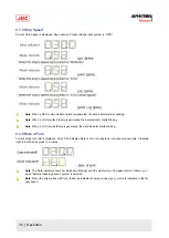
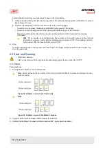
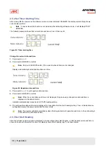
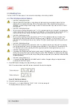
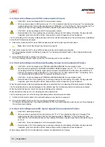
Figure 29: Repeater Compass
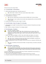
Prior to synchronization of the Master Compass carry out the Repeater Stepper Output Check (Test Mode B).
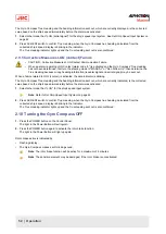
To stop the master compass. See Turning the Gyro Compass OFF on page 52. The phantom ring starts rotating
360˚.
The Sensitive Element rotor should have stopped spinning completely (approx. 4 minutes), for preparation of the various
tests and adjustments.
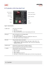
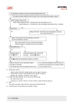
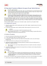
1. Press the DISP + SET buttons on the operating panel simultaneously.
2. Press the POWER switch (Test Mode B).
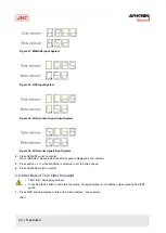
3. Set
0˚,
90˚,
180˚
and
270˚
by pressing the
▼
▲
buttons and press ACK/ENT.
Note Step signals reception instrument (repeater compass) should follow up within
0.5˚.
4. Turn "OFF" each repeater switch.
5. Adjust it to the Gyro Compass True Heading.
6. Turn "ON" the Repeater Switch.
41 | Operation
Summary of Contents for Alpatron AlphaMidiCourse
Page 1: ...AlphaMidiCourse Gyro Compass Installation and Operation Manual www jrc am ...
Page 68: ...5 1 1 Outline Control Unit One Gyro Compass System Figure 41 Control Box 68 Appendices ...
Page 69: ...5 1 2 Operating Panel Figure 42 Operating Panel 69 Appendices ...
Page 70: ...5 1 3 Master Compass Figure 43 Main Unit 70 Appendices ...
Page 71: ...Figure 44 Open Gyro Compass 71 Appendices ...
Page 73: ...5 1 5 Connection Diagram Figure 46 Connection Diagram 73 Appendices ...
Page 74: ...5 1 6 Cable Diagram Figure 47 Cable Diagram 74 Appendices ...
Page 75: ...5 1 7 Installation Drawing Figure 48 Installation Drawing 75 Appendices ...
Page 76: ...5 1 8 Terminal Board Figure 49 Terminal Board 76 Appendices ...

