2.8 Operation Procedure of Master Compass Power Switch (Option)
•
CAUTION - System Selection
•
System selection (switching) may cause large change of True Heading. When on automatic steering, first turn
the steering mode of the automatic steering system to "MANUAL" to prevent a large course change. Confirm
the area around the ship is clear and turn to "AUTO" steering again.
•
CAUTION - Operating Procedure Master Compass Switch (Option)
•
DO NOT touch the Master Compass Power Switch while the Gyro Compass operates normally, to prevent
serious damage to the sensitive element, reduce the life cycle of the product, or unexpected problems. The
Master Compass Power Switch must be operated only when the master compass is in abnormal condition.
With the optional Master Compass Power Switch the running of the compass can be stopped and the output of heading
information to the external heading sensor can be changed, if connected. This minimizes the loss of heading signal when
any abnormal condition or failure occurs in the master compass. The Master Compass Power-off Switch is located inside
the optional Power Supply Unit.
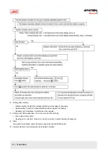
When any abnormal condition or failure occurs in the master compass, operate the Gyro Compass as follows:
2.8.1 Operation Procedure
1. Change the heading output to external heading sensor system (GPS compass or magnetic compass). see System
2. Turn the master compass power switch, optionally provided in the steering stand or the control unit, to OFF.
•
CAUTION
•
DO NOT turn the main power-on switch on the operation panel to OFF.
Note Although the alarm
code「3」or「A」will
appear and be kept indicating, the output with the external
heading sensor selected will be transmitted and kept on.
2.8.2 Return Procedure
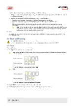
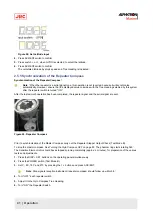
1. First turn the steering mode of the steering control system to HAND.
2. Turn the Compass Power Switch of the operation panel to OFF.
3. Turn the Master Compass Power Switch, located either in the steering stand or in the control unit of the Gyro
Compass, to ON.
4. Turn the Power Switch in the operation panel of the Gyro Compass to ON.
5. Synchronize the repeater heading with the heading information provided from the external heading sensor as
selected in (1) changeover procedure.
Note changeover to the Gyro Compass heading should be done in about three hours after re-starting the
Gyro Compass.
6. Synchronize the heading of each repeater with the heading of the Gyro Compass, once the heading information is
changed on the Gyro Compass
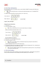
2.9 Alarm
•
CAUTION - Alarms
•
When the following alarms are activated, the heading information from this system may not be sent at all,
or may have a large error. All units operated by the heading information from this system (in particular, the
automatic steering system, etc.) should be operated immediately according to the individual emergency
operating procedure.
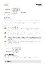
When an alarm is activated, the buzzer will provide an audible alarm and an alarm code will be displayed in the indicator.
1. Confirm alarm code and press ACK/ENT switch to stop buzzer, when an alarm has been generated.
47 | Operation
Summary of Contents for Alpatron AlphaMidiCourse
Page 1: ...AlphaMidiCourse Gyro Compass Installation and Operation Manual www jrc am ...
Page 68: ...5 1 1 Outline Control Unit One Gyro Compass System Figure 41 Control Box 68 Appendices ...
Page 69: ...5 1 2 Operating Panel Figure 42 Operating Panel 69 Appendices ...
Page 70: ...5 1 3 Master Compass Figure 43 Main Unit 70 Appendices ...
Page 71: ...Figure 44 Open Gyro Compass 71 Appendices ...
Page 73: ...5 1 5 Connection Diagram Figure 46 Connection Diagram 73 Appendices ...
Page 74: ...5 1 6 Cable Diagram Figure 47 Cable Diagram 74 Appendices ...
Page 75: ...5 1 7 Installation Drawing Figure 48 Installation Drawing 75 Appendices ...
Page 76: ...5 1 8 Terminal Board Figure 49 Terminal Board 76 Appendices ...

