Part Name
Part No.
Belt
3107.9160
HRZC PWB
3107.9162
Inverter PWB
3107.9164
Slip Ring
3107.9166
Flexibel Wire (east)
3107.9168
Gpower PWB
3107.9170
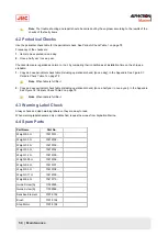
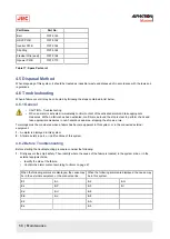
Table 17: Spare Parts List
4.5 Disposal Method
When disposing of this system, it should be treated as industrial waste and disposed of in accordance with the laws and
regulations.
4.6 Troubleshooting
When a failure occurs it may be corrected by following the steps contained in list below.
4.6.1 General
•
CAUTION - Troubleshooting
•
When an alarm is activated, immediately confirm content of the activated alarm and take appropriate
measures.
●When
a failure has been activated, confirm area around the ship is clear to perform check and
take appropriate measures in non-hazardous sea area, stopping the ship as a rule.
Two things must be considered when a failure has become apparent in this system, or in the connected external
equipment:
1. An alarm is displayed in this system.
2. A failure exists in part, or in all functions of this system.
4.6.2 Before Troubleshooting
Before starting the troubleshooting procedure consider the following:
1. Firstly ensure the ship's safety. Then identify where the cause of the failure is located; in the system side, or in the
external equipment side.
•
Identify the side of the failure.
•
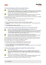
Confirm the alarm content according to Alarm on page 47.
When the following alarms are displayed, the cause may
be in the external equipment, or the connected line.
When the following alarms are displayed, the cause may
be in this system.
E-1
E-n
E-2
E-G
E-c
E-P
E-3
E-r
E-d
E-U
E-6
E-E
E-u
E-8
E-F
E-A
E-L
E-b
59 | Maintenance
Summary of Contents for Alpatron AlphaMidiCourse
Page 1: ...AlphaMidiCourse Gyro Compass Installation and Operation Manual www jrc am ...
Page 68: ...5 1 1 Outline Control Unit One Gyro Compass System Figure 41 Control Box 68 Appendices ...
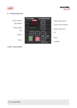
Page 69: ...5 1 2 Operating Panel Figure 42 Operating Panel 69 Appendices ...
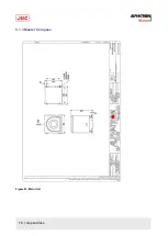
Page 70: ...5 1 3 Master Compass Figure 43 Main Unit 70 Appendices ...
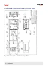
Page 71: ...Figure 44 Open Gyro Compass 71 Appendices ...
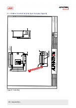
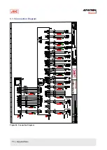
Page 73: ...5 1 5 Connection Diagram Figure 46 Connection Diagram 73 Appendices ...
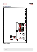
Page 74: ...5 1 6 Cable Diagram Figure 47 Cable Diagram 74 Appendices ...
Page 75: ...5 1 7 Installation Drawing Figure 48 Installation Drawing 75 Appendices ...
Page 76: ...5 1 8 Terminal Board Figure 49 Terminal Board 76 Appendices ...

