68 | Specifications
4 Maintenance
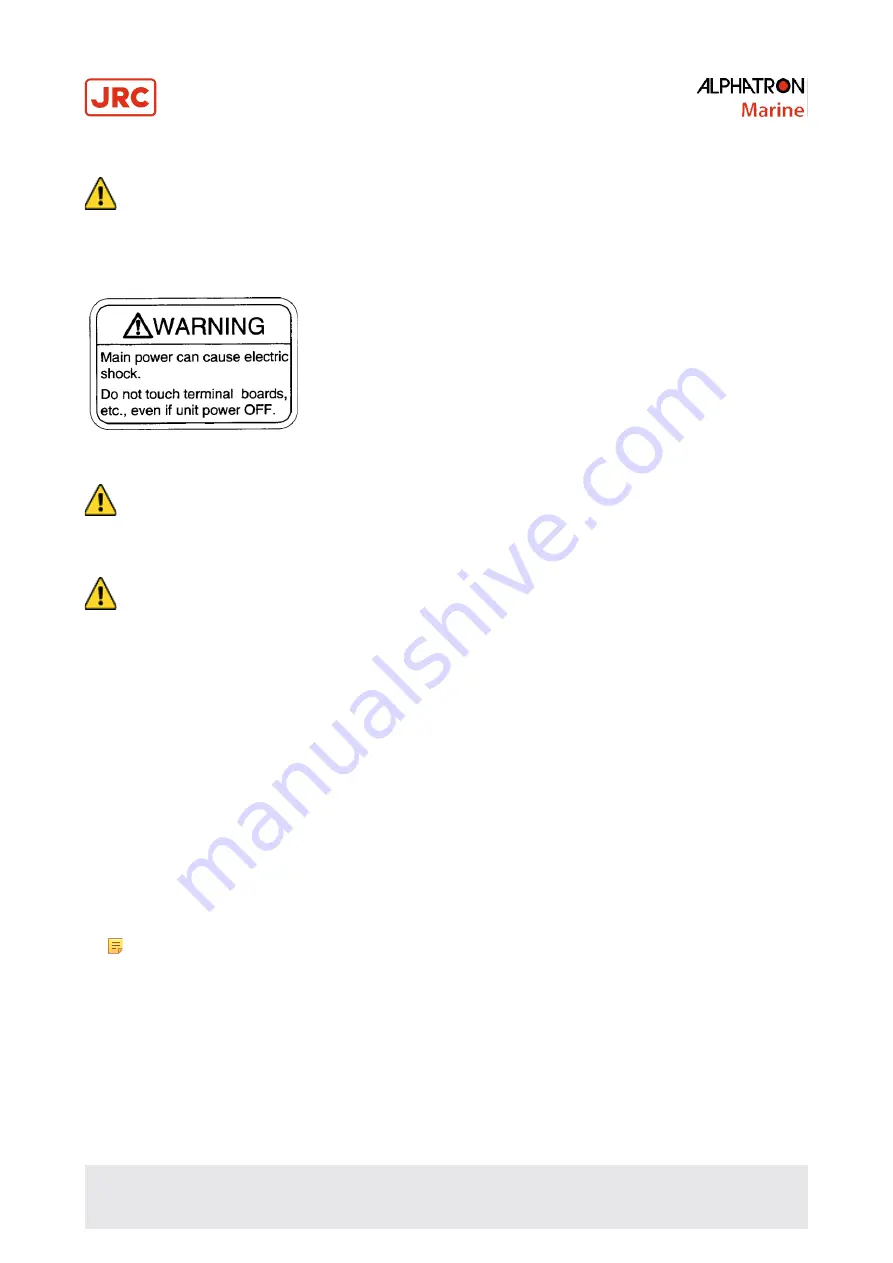
• WARNING - Maintenance
• During maintenance or check of the product, touching internal parts may cause electric shock, because
the ship's power supply is still connected to the system distribution board, even if the main power switch of
this product is turned "OFF". Do not touch internal parts such as terminal boards, power supply unit, etc. If
necessary, disconnect the power cable from the ship’s distribution board. A warning label is attached to point
out this danger.
Figure: Warning Label
• CAUTION - Maintenance and check
• Main units of this system consist of electronic circuits of high reliability. If a failure occurs, perform the check
and maintenance as described in this chapter and correct the fault(s) to prevent further risk of failure and to
maintain the system's performance. Failure to carry this out, the detection of the failure sign will be delayed
and may cause accidents such as collision or grounding.
• CAUTION - Prohibition
• Do not use insulation tester or other device to test system insulation as it will damage internal electrical
components. Always disconnect the wiring connected to this system before testing related power distribution
lines with such testers.
4.1 General Procedures
This system consists of carefully selected parts based on safety design. Periodical checks (operational checks) and
maintenance must still be performed for long term satisfactory operation.
Main purpose of the periodical checks and maintenance is to catch signs of equipment failure at an early stage. Repairs
on call in port as a result of these checks will prevent unexpected failures to a minimum while sailing.
For the periodical checks and maintenance of the equipment connected to this system, like the automatic steering
system, magnetic compass system, etc., refer to the separate individual Operator's Manuals.
Record content of the checks and maintenance performed in the logbook.
1.
Assign a person in charge of periodical checks and maintenance for this system to be executed under his
responsibility.
2.
Check and re-tighten loosened screws of mechanical connections, due to body shock and resonance vibration.
3.
Re fix parts, fixing screws, mounting parts, reinsert connectors and repair loosened cables and wires.
Note
Most parts used in the main sections of this system are electronic (electric) parts. Occurrence of
electronic parts trouble themselves is very seldom, and troubles in mounting sections of electronic (electric)
parts, being about to disconnect wires at roots or lead wires of electric parts, occur easily due to hull body
shock or resonance vibration. These are the points to be checked.
4.
Record strange motions, smells, sounds and heat generation, etc. different from those that exist in normal operations.
5.
Request repair from Alphatron Marine Service Engineer, or agent.
6.
Have the system checked periodically by Alphatron Service Engineer, or agent.
7.
Have the checklist table and the logbook evaluated by the engineer.
Summary of Contents for ALPHAMIDICOURSE Mk2
Page 80: ...80 Appendices 6 1 1 Dimensions of Control Unit...
Page 81: ...81 Appendices 6 1 2 Dimensions of Master Compass...
Page 82: ...82 Appendices 6 1 3 Master Compass without housing...
Page 84: ...84 Appendices 6 1 5 Connection Diagram...
Page 85: ...75 Appendices 6 1 6 Cable Diagram...
Page 86: ...76 Appendices 6 1 7 Installation Drawing...
Page 88: ...78 Appendices AlphaMidiCourse Mk2 Check Maintenance Sheet...
Page 89: ...79 Appendices AlphaMidiCourse Mk2 Check Maintenance Sheet...
Page 90: ...80 Appendices AlphaMidiCourse Mk2 Check Maintenance Sheet...
Page 91: ...81 Appendices AlphaMidiCourse Mk2 Check Maintenance Sheet...
Page 92: ...82 Appendices AlphaMidiCourse Mk2 Check Maintenance Sheet...
Page 95: ...85 Appendices 6 4 Return Slip Sensitive element...
Page 96: ...86 Appendices...
Page 99: ......


