3.5
How to Determine Depths and Sample Scan Test Data
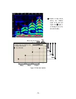
The reflected waves
shown in the scan
test example in Figure 3-16 are reflections of rebar. (
↓
position)
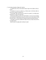
The position of the object to be probed (e.g., reinforcing steel) in the traveling direction is
determined as the peak of the reflected wave.
An approximate depth (covering depth) of the object to be probed (e.g., reinforcing steel) is
determined as the center of the reflected wave.
Perform depth calibration (see section
3.2.6 “Depth Calibration”) to reduce the error in the depth
(covering depth) of the object being probed (such as rebar). Use the A mode waveform from BA
mode (see section
3.3.1 “Mode Switching”) to determine the position of the object to be probed.
The position of the object to be probed (such as rebar) is shown by the peak on the right side of
the A mode waveform.
Match the cursor to the peak position to determine the depth.
‑ 52 ‑
Summary of Contents for Handy Search NJJ-95B
Page 1: ...Handy Search Instruction Manual...
Page 8: ...Appearance of the NJJ 95B vii...
Page 21: ...Rear view Units in trigonometry mm 9...
Page 24: ...8 14 15 Figure 2 2 Side View 16 17 14 18 Figure 2 3 Rear View 12...
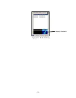
Page 73: ...Display of thumbnails Figure 3 17 CF Control Screen 61...
Page 83: ...B Terminals ACharge confirmation mark Figure 3 22 Battery Pack 71...
Page 85: ...Shutter Charge lamp Figure 3 23 Battery Charger 73...
Page 96: ...Concrete Rebar D 75mm L 75mm D 75mm Difficult to implement 84...
Page 103: ...Dimensions Weight About 149 W x 147 H x 216 D mm Approximately 1 1kg 91...


