iii
●
Before Operation
●
Pictorial Indication
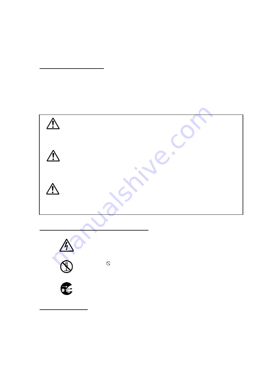
Various pictorial indications are included in this manual and are shown on this equipment so
that you can operate them safely and correctly and prevent any danger to you and / or to
other persons and any damage to your property during operation. Such indications and their
meanings are as follows.
Please understand them before you read this manual:
This indication is shown where any person is supposed to
be imminent of danger to which the person owes the death
or the serious injury if this indication is neglected and this
equipment is not operated correctly.
This indication is shown where any person is supposed to
be in danger of being killed or seriously injured if this
indication is neglected and this equipment is not operated
correctly.
This indication is shown where any person is supposed to
be injured or any property damage is supposed to occur if
this indication is neglected and this equipment is not
operated correctly.
Examples of pictorial indication
The
△
mark represents CAUTION (including DANGER and WARNING).
Detailed content of CAUTION (“Electric Shock” in the example on the
Electric left.) is shown in the mark.
The mark represents prohibition.
Detailed content of the prohibited action (“Disassembling Prohibited” in
Disassembling the example on the left) is shown in the mark.
The
●
mark represents instruction.
Detailed content of the instruction (“Disconnect the power plug” in the
example on the left) is shown in the mark.
Warning label
There is a warning label on the top cover of the equipment.
Do not try to remove, break or modify the label.
WARNING
CAUTION
DANGER
Summary of Contents for JFS-280
Page 2: ......
Page 3: ...A General Information Before you begin 7ZPNA2401...
Page 4: ......
Page 34: ......
Page 36: ......
Page 38: ...1 Overview of the equipment 1 2 1...
Page 43: ...1 7 1 Overview of the equipment 1 Diagram 1 1 Exterior view of the NWZ 207 display unit...
Page 44: ...1 Overview of the equipment 1 8 1 Diagram 1 2 Exterior view of the NCH 578 keyboard...
Page 47: ...1 11 1 Overview of the equipment 1 Diagram 1 5 Exterior view of the NKF 2800 hoisting device...
Page 50: ...2 Names and Functions of Parts 2 2 2...
Page 90: ...3 Operating procedures 3 28 3...
Page 148: ...5 Adjusting How Images Appear 5 34 5...
Page 267: ...7 33 7 Other Items 7...
Page 274: ...7 Other Items 7 40 7 7 6 2 Test Ring Number 7 6 3 Reservation Settings...
Page 282: ...8 Maintenance and inspections 8 2 8...
Page 288: ...8 Maintenance and inspections 8 8 8...
Page 290: ...9 Malfunctions and after sales service 9 2 9...
Page 294: ...9 Malfunctions and after sales service 9 6 9...
Page 296: ...10 Disposal 10 2 10...
Page 298: ...10 Disposal 10 4 10...
Page 300: ...11 Specifications 11 2 11...
Page 306: ...11 Specifications 11 8 11...
Page 308: ...12 Other 12 2 12...
Page 309: ...12 3 12 Other 12 12 1 List of Menus...
Page 310: ...12 Other 12 4 12...
Page 311: ...12 5 12 Other 12...
Page 312: ...12 Other 12 6 12...
Page 313: ...12 7 12 Other 12...
Page 314: ...12 Other 12 8 12...
Page 315: ...12 9 12 Other 12...
Page 316: ...12 Other 12 10 12...
Page 317: ...12 11 12 Other 12...
Page 318: ...12 Other 12 12 12...
Page 319: ...12 13 12 Other 12...
Page 320: ...12 Other 12 14 12 12 2 Setting the Colors of the Sonar Display...
Page 321: ...12 15 12 Other 12...
Page 322: ...12 Other 12 16 12 12 3 Setting the Colors of the Fish Finder Display...
Page 323: ...12 17 12 Other 12 12 4 Sonar Range and Initial Setting Values for the Fish Finder Range...
Page 326: ...12 Other 12 20 12...
Page 327: ......


