6-31
S7 TX DELAY
0 MS
This menu controls the interval between serial data messages. The delay can be used to lower
data rate for slow receiver devices unable to handle messages back to back. The value is
adjustable in 10 ms steps from 0 up to 60-70 ms (default delay is 0 ms). For maximum
throughput the value shall be set as low as possible. When using the MFD5 we recommend
setting this value to 60-70ms.
S8, BT Speed Inp
S8 BT SPEED INP
LOG
Currently not implemented, but will extend the use of the Sig. Distributor to also calculate
docking-log information from other speed sources.
S9 – S14, Pulses
S9 PULSE A
WTL 200 P / NM
to
S14 PULSE F
BTR 200 P / NM
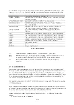
There are 6 different pulse timers (A-F) used to generate speed pulses that can be chosen for
relay and opto outputs. Following listed speeds can be set under Menu S9 – S14.
Pulse timer settings Function
WTL 100P
Longitudinal STW 100 pulses / NM
WTL 200P
Longitudinal STW 200 pulses / NM (Default for Pulse timer A)
WTL 400P
Longitudinal STW 400 pulses / NM
WTL 500P
Longitudinal STW 500 pulses / NM
WTT 100P
Transversal STW 100 pulses / NM
WTT 200P
Transversal STW 200 pulses / NM (Default for Pulse timer B)
WTT 400P
Transversal STW 400 pulses / NM
WTT 500P
Transversal STW 500 pulses / NM
WTR 100P
Resulting STW 100 pulses / NM
WTR 200P
Resulting STW 200 pulses / NM (Default for Pulse timer C)
WTR 400P
Resulting STW 400 pulses / NM
WTR 500P
Resulting STW 500 pulses / NM
BTL 100P
Longitudinal SOG 100 pulses / NM
BTL 200P
Longitudinal SOG 200 pulses / NM (Default for Pulse timer D)
BTL 400P
Longitudinal SOG 400 pulses / NM
BTL 500P
Longitudinal SOG 500 pulses / NM
BTT 100P
Transversal SOG 100 pulses / NM
BTT 200P
Transversal SOG 200 pulses / NM (Default for Pulse timer E)
BTT 400P
Transversal SOG 400 pulses / NM
BTT 500P
Transversal SOG 500 pulses / NM
Summary of Contents for JLN-900
Page 2: ......
Page 12: ...x This page is intentionally blank ...
Page 17: ...2 1 JLN 900 Technical Description ...
Page 23: ...2 7 sigbel ...
Page 30: ...2 14 This page is intentionally blank ...
Page 31: ...3 1 JLN 900 Technical Specification ...
Page 38: ...3 8 This page is intentionally blank ...
Page 39: ...4 1 JLN 900 Installation of Transducer and Bottom Parts ...
Page 59: ...4 21 Transducer and Valve Cover mounted Sea Valve fully opened ...
Page 63: ...4 25 Fig 1 3 Aligning Transducer Connecting Tube ...
Page 76: ...4 38 Mounting Sea Valve on Upper Flange DB ...
Page 81: ...4 43 Gasket Seal 2 ...
Page 83: ...4 45 Transducer and Valve Cover mounted Sea Valve fully opened ...
Page 86: ...4 48 Tube Bracket in its final position with Transducer flush seated ...
Page 88: ...4 50 Fig 2 5 Aligning Transducer Connecting Tube ...
Page 92: ...4 54 This page is intentionally blank ...
Page 93: ...5 1 JLN 900 Installation of NJC 80 Sig Processor ...
Page 150: ...6 50 This page is intentionally blank ...
Page 151: ...7 1 JLN 900 Display Technical Description ...
Page 167: ...7 17 No Name Default setting Function SD 4 2 SD 4 3 SD 4 4 there are remote systems connected ...
Page 179: ...8 1 JLN 900 Analog Display Technical Manual ...
Page 183: ...8 5 2 1 Main Dimensions NWW 828 Analog Display ...
Page 184: ...8 6 2 2 Dimmer Potentiometer connection Analog Display ...
Page 186: ...8 8 This page is intentionally blank ...
Page 187: ...9 1 JLN 900 Menu System ...
Page 208: ...9 22 This page is intentionally blank ...
Page 209: ...10 1 JLN 900 WATER TRACK Technical Manual including Menu system ...
Page 233: ...11 1 JLN 900 IEC 61162 NMEA 0183 User Guide ...
Page 254: ...11 22 This page is intentionally blank ...
Page 255: ...12 1 JLN 900 Harbour Acceptance Test ...
Page 266: ...12 12 This page is intentionally blank ...
Page 267: ...13 1 JLN 900 Calibration and Sea Acceptance Test ...
Page 280: ...13 14 This page is intentionally blank ...
Page 281: ...JLN 900 system drawings 14 1 ...
Page 289: ...CFT 780 4 TRANSDUCER 40m 14 9 ...
Page 290: ...NKF 980 Sea Valve 14 10 ...
Page 291: ...NKF 980 Sea Valve 14 11 ...
Page 292: ...NWW 82 MAIN DISPLAY 14 12 ...
Page 293: ...DISPLAY 3 1 87 14 13 ...
Page 294: ...NCM 1080 DIMMER UNIT 14 14 ...
Page 295: ...15 1 JLN 900 Description labels and drawings ...
Page 300: ...15 6 This page is intentionally blank ...
Page 301: ...16 1 Annex JLN 900 Speed Log System Manual ...
Page 302: ...16 2 Annex Table of contents ANNEX I EQUIPMENT RECYCLING 3 ANNEX II ENERGY SAVING 5 ...
Page 306: ...16 6 This page is intentionally blank ...
Page 307: ......


