background image


10-10 

4.2.4  Self-Diagnosis 

After ten speed measurements, the self-diagnosis is performed. The self-diagnosis checks: 

x


Transmitter 

x


Receiver 

x


Internal signal data paths 

x


ADC (Analogue to Digital Converter) 

x


High speed (LVDS) interface integrity 

x


Transducer 

x


External noise 

x


Input signal balance 

If a detected failure persists for at least 14 diagnosis cycles, a diagnostic code will be sent as an 
NMEA telegram with the proprietary sentence PSALW. Also the ALERT LED at the WATER 
TRACK U board will be turned on. 

4.3  Menu system 

The WATER TRACK U has an internal menu system that can be accessed via a serial interface 
connected to a remote display such as the NWW-82 Speed log Master Display. 
The information is presented as two lines with 16 characters. All WATER TRACK U settings, 
calibration, etc., can be changed through the menu system. 
The settings are stored in non-volatile memory and will therefore also be active after a reboot 
or power shut-down. 

4.3.1  Accessing the Menu system 

Here follows a short guide to access the menu system in WATER TRACK U via an NWW-82 
Speed Log Master Display. (For a detailed description of the NWW-82 menu system, see 
Section 7

)

4.3.2  Reaching NWW-82 Menu Mode  

The Mode window of the NWW-82 Display can be set to Menu Mode, which is used for 
internal settings of the display and can be used to connect to a remote unit such as WATER 
TRACK U. 
The Menu Mode is reached by pressing the 

Mode

 button for minimum 5 seconds. The Mode 

Window will show the text “PRESS ENTER FOR MENU”. Then press the 

Enter

 (4

th

 button 

from left) within 5 seconds. 
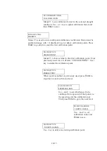
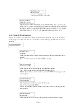
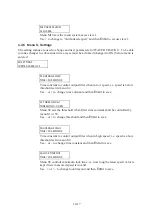
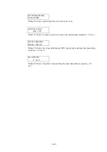
The Mode Window will now show the start menu in the NWW-82. The six buttons under the 
Mode Window have now got alternative functions. The alternative functions are lit in red text 
below relevant button.  
The buttons now have the following functions: 

Summary of Contents for JLN-900

Page 1: ...EED LOG SPEED LOG ISO 9001 ISO 14001 Certified MAR 2020 Edition 1 CODE No 7ZPNA3210 Not use the asbestos For further information contact URL Head office http www jrc co jp eng Marine Service Department 1 7 32 Tatsumi Koto ku Tokyo 135 0053 Japan tmsc jrc co jp 81 50 3786 9201 e mail One call ...

Page 2: ......

Page 3: ...G LQWR WKH LQVLGH RI DSSDUDWXV PDNH VXUH WKDW LQWHUQDO SDUWV DUH QR ORQJHU FKDUJHG WUD SURWHFWLRQ LV HQVXUHG E ZHDULQJ GU FRWWRQ JORYHV DW WKLV WLPH QRWKHU LPSRUWDQW SUHFDXWLRQ WR REVHUYH LV WR NHHS RQH KDQG LQ RXU SRFNHW DW D WLPH LQVWHDG RI XVLQJ ERWK KDQGV DW WKH VDPH WLPH W LV DOVR LPSRUWDQW WR VHOHFW D VHFXUH IRRWLQJ WR ZRUN RQ DV WKH VHFRQGDU HIIHFWV RI HOHFWULFDO VKRFN KD DUGV FDQ EH PRUH V...

Page 4: ... 4 Lay the patient on the back loosening the necktie clothes belts and so on 5 a Feel the patient s pulse b Check the heartbeat by bringing your ear close to the patient s heart c Check for respiration by bringing your face or the back of your hand to the patient s face d Check the size of patient s pupils 6 Opening the patient s mouth remove artificial teeth cigarettes chewing gum etc if any With...

Page 5: ...a deep breath and blow into the nostril through the pipe with the other nostril and the mouth completely closed 6 The patient may stand up abruptly upon recovering consciousness Keep the patient lying calmly giving him or her coffee tea or any other hot drink but not alcoholic drink to keep him or her warm Mouth to mouth artificial respiration with the patient s head lifted 1 1 Lift the back part ...

Page 6: ...condary disasters Electric shock is needed Check for response Call while tapping the shoulder Breathing Recovery position Lay the injured or ill person on his her side and wait for the arrival of the emergency services Electric shock is not needed Not responding or can not judge Ask for help Make an emergency call Ask to bring an AED Delivery of electric shock Listen to the appeal of the injured o...

Page 7: ...es or there is some response or gesture determine it as responding But if there is no response or gesture determine it as not responding 3 If responding a Give first aid treatment 4 If not responding a Ask for help loudly Ask somebody to make an emergency call and bring an AED Somebody has collapsed Please help Please call an ambulance Please bring an AED If there is nobody to help call an ambulan...

Page 8: ...pproximately 5 cm b Combination of 30 chest compressions and 2 rescue breaths 1 Untrained first aiders only performs chest compressions 2 If trained first aiders has the technique and a will to perform rescue breaths give 2 rescue breaths after performing 30 chest compressions 3 If there is a fear of infection use a mouthpiece for rescue breathing and other protective devices to prevent infections...

Page 9: ...om the chest abdomen and arms b Open the package of electrode pads peel the pads off and securely place them on the chest of the injured or ill person with the adhesive side facing the chest If the pads are not securely attached to the chest the AED may not function Paste the pads exactly at the positions indicated on the pads If the chest is wet with water wipe dry with a dry towel and the like a...

Page 10: ...esume chest compressions a Resume chest compressions by following the voice prompts of the AED With each compression Depress the chest wall to a depth of approximately 5 cm Perform uninterrupted chest compressions of 30 at the rate of about 100 to 120 times per minute 13 Automatic electrocardiogram analysis a When 2 minutes have elapsed since you resumed cardiopulmonary resuscitation CPR the AED a...

Page 11: ...4480 Sig Distributor 7 Display Technical Dsecription 8 Analogue Display Technical Manual 9 Menu System 10 Water Track Unit Assembly Technical Manual and Menu System 11 IEC 61162 NMEA 0183 User Guide 12 Harbour Acceptance Test 13 Calibration and Sea Acceptance Test 14 JLN 900 System drawings 15 JLN 900 System description labels and drawings 16 JLN 900Manual Annex I Equipment recycling II Energy sav...

Page 12: ...x This page is intentionally blank ...

Page 13: ...ed in various IMO documents However equipment may sometimes fail or work outside its performance specification due to component malfunction or depending on other factors JRC will not take any responsibility if this equipment is used in such a way that it s normal or abnormal function causes damage or creates situations that can be dangerous All specifications given in this manual are subject to ch...

Page 14: ...r units Outputs available are serial NMEA relay contacts opto couplers and analogue output The Sig Distributor can also take data from a connected turn rate gyro If the docking log option in the Sig Distributor is enabled the data from the log and the gyro are combined to create also docking log information that can be used by the docking log display MainDisplay NWW 82 Main Display are versatile i...

Page 15: ...e to Sig Distributor adds docking log functionality Bridge Wing Docking Display Option Bridge Wing Docking Display Option Engine Control Room Main Display Speed Log Display Option Wheelhouse Main Display Master Display STW Device y y Main Display Speed Log Display SOG Device Sig Distributor Bow Sig Processor ...

Page 16: ...rol unit Speed Log Master Display Note The JLN 900 system must consist of at least two NWW 82displays one marked STW Device and one marked SOG Device Each of these displays shall be connected according to JLN 900 drawings in this manual Optional items for a system Unit number Name of unit Description NWW 85 Docking Display Serial Digital SOG STW docking log display 5HTAQ00006 BULKHEAD M BOX Bulkhe...

Page 17: ...2 1 JLN 900 Technical Description ...

Page 18: ...mission reception 2 3 2 2 Depth measurement 2 4 2 2 1 Seek mode 2 4 2 2 2 Lock mode 2 4 2 3 Speed measurement 2 5 2 3 1 Speckle pattern 2 5 2 3 2 Correlation technique 2 10 3 CFT 780 TRANSDUCER 2 11 4 NJC 80 SIG PROCESSOR 2 12 4 1 BTU PCB 2 13 4 2 WTU Assy 2 13 4 3 Data transmission reception 2 13 ...

Page 19: ...surement 1 1 Acoustic transmission reception The correlation speed log uses acoustic waves in water The transducer is mounted flush with the hull see figure below Waves are transmitted from the piezo electric elements into the water down to the sea bed The sea bed reflects the signal back to the piezo electric elements which acts as receivers when not used as transmitters We use broad antenna lobe...

Page 20: ...smit pulse the receiver is sampled at regular intervals The echo will have the same length as the transmitted pulse The log correlates the transmitted pulse with the echo to form an echo function The peak of this function corresponds to the time it takes for the pulse to travel from the hull to the sea bed and back If a valid echo is found the log enters the depth lock mode Depth seek mode Transmi...

Page 21: ...The receiving sensor elements will see a speckle pattern First we discuss this pattern and then correlation technique to estimate the speed 1 3 1 Speckle pattern A coherent beam is transmitted towards the sea bed This means that the signal has both intensity and phase information When the signal is reflected back the signal will be modulated both in amplitude and phase Each reflector will give a p...

Page 22: ...they will support each other The same effect is used in holography where also both phase and amplitude information is used Thus we get a holographic pattern on the hull of the ship with loud and silent spots It can be shown that the size of a loud spot is typically the same as the transmitter area The receivers measure the intensity as they travel over this pattern One such computer simulated patt...

Page 23: ...2 7 sigbel ...

Page 24: ...2 8 This pattern may also be visualised as a map with valleys and mountains representing the intensity at the position see figure below sigbel ...

Page 25: ...low shows the difference at 45º and a 90º relative to the motion The similarity decreases and the signal time displacement decreases The ship moves the transducer during both transmit and receive This will be seen as a doubled speed of the speckle pattern during receive The interference pattern will give signals with 100 modulation that are easy to detect Side lobes give no false speed The broad b...

Page 26: ...er than the maximum pulse length we cannot calculate the speed directly This limit is when the speed in knots multiplied with the depth in metres is less than 41 In this case signal statistics is used to estimate the speed Accuracy is lower in this mode The two axis log calculates the velocity in six different directions and then weights them together to find the longitudinal and transversal compo...

Page 27: ...nts are clearly divided into the five SOG elements and the two STW elements in a separate casing Electrically each sensor element is connected via a matching transformer to a separately shielded twisted pair For transmission with the low frequency SOG part a separate transmit cable pair is used that connects the signal to the three transducer elements used for transmission The positioning of the t...

Page 28: ...cessor The Electronics Unit is from the functional point of view divided into two more or less separated units SOG unit BTU T2F T2R and transmitter integrated on T M board and STW unit WTU Assy Block diagram is shown below ...

Page 29: ...sed by the speed log are described in detail in document 700164 The following NMEA sentences are transmitted in a standard setup Serial port Function NMEA sentences transmitted NMEA0 TxBT Terminal 102 103 This output carries basic information Can be used by external users VDVBW VDDPT NMEA1 RxMain Terminal 105 106 Main input NMEA2 TxMain Terminal 108 109 Main output also containing internal informa...

Page 30: ...2 14 This page is intentionally blank ...

Page 31: ...3 1 JLN 900 Technical Specification ...

Page 32: ...er the Ground true speed 3 3 2 2 Accuracy of measurement 3 3 2 2 1 STW 3 3 2 2 2 SOG 3 3 2 3 Functional limitations 3 4 2 3 1 STW 3 4 2 3 2 SOG 3 4 3 ENVIRONMENTAL CONDITIONS 3 5 4 INTERFACES 3 5 4 1 Serial interface sentences 3 5 4 1 1 NQA 4480 Sig Distributor 3 5 4 1 2 NJC 80 Sig Processor 3 5 4 1 3 NWW 82 Main Display 3 5 4 2 Relays opto couplers and analogue outputs 3 6 5 CALIBRATION 3 6 6 POW...

Page 33: ...eater or equal to 3 m beneath the transducer Speed range 50 knots sensed Speed Through the Water 2 1 2 SOG Speed Over the Ground true speed Frequency 150 kHz Depth requirement greater or equal to 2 m beneath the transducer Depth range nominally 2 250 m below transducer Speed range 40 knots in any direction 2 2 Accuracy of measurement 2 2 1 STW Speed error relative to sensed water speed 0 1 knot or...

Page 34: ...tic reflectors are present in the water such as muddy water in rivers and canals river inlets harbour areas and similar shallow water areas with soft bottom structures When normal conditions are not met the STW may indicate zero speed at low speed or invalid status with digital indicators displaying 2 3 2 SOG The SOG part of the system is in operation when SOG speed is shown on the master display ...

Page 35: ... NQA 4480 Sig Distributor NQA 4480 is intended to be connected to other systems It has 23 serial outputs fed from 13 separately buffered drivers NQA 4480 has various options to perform signal processing and calculations from the speed log and other inputs Please refer to NQA 4480 Technical Manual for details 4 1 2 NJC 80 Sig Processor NJC 80 is connected to NQA 4480 It has one serial output from S...

Page 36: ...speed log via the Speed Log Master Display as appropriate for the SOG and STW respectively STW range 50 00 to 50 00 of sensed speed in 0 01 steps Up to 3 different draught conditions Up to 10 speed calibration points SOG range 50 00 to 50 00 of sensed speed in 0 01 steps SOG transducer angle range 180 0º to 180 0º in 0 1º steps The STW speed log generally needs calibration correction on all ships ...

Page 37: ...y Voltage 12 24 V DC 10 32 Power consumption typical 1 5 W peak 3 W powered from the LPU2 Dimensions WxHxD 144x144x16 mm Compass safe distance 0 3 m IP class front side IP66 if mounted in BMB Weight 0 6 kg 7 Liability All equipment described in this manual is designed for use on board ships and fulfils relevant requirements specified by International Maritime Organization IMO However equipment may...

Page 38: ...3 8 This page is intentionally blank ...

Page 39: ...4 1 JLN 900 Installation of Transducer and Bottom Parts ...

Page 40: ...1 General 3 2 Transducer location requirements 5 3 Installation of Bottom Parts 7 4 Mounting Set Single Bottom Sea Valve MSSBSV H 10 5 Mounting Set Double Bottom Sea Valve MSDBSV H 27 6 Recommended spares and maintenance 52 ...

Page 41: ...tion General mounting recommendations Use universal thread locking liquid e g Loctite 243 or equal when mounting Studs PS M16x40 Part No 71 22021 00 into flange not grease Apply MoS2 grease on rest of screws threads Use Vaseline Silicone grease or similar to lubricate the Lip Seals Recommended torque M10 approx 35Nm M12 approx 57Nm M16 approx 150Nm After mounting just before Sea trial and at every...

Page 42: ...ng the Guide Ring positions the Transducer flush with the underside of the hull With the SeaValve arrangement the intention is to provide retraction removal for service maintenance or replacement of the Transducer while the ship is still afloat thus dry docking is not needed The Connecting Tube with a Tube Bracket assembly holds the Transducer fixed in its position and has a watertight Cable Gland...

Page 43: ...rtment in which the Transducer is installed may be sealed by a manhole or hatch but the compartment must always be accessible for service 6 The Transducer cable must be installed in an accessible way to allow retraction dismounting incase of service or replacement of a defective Transducer Excessive cable length shall be left uncut and coiled i e one coil loop close to the Sea Valve Transducer and...

Page 44: ...layer is not uniform around the ship and can range from a few millimetres near the bow to more than one metre at the stern on a large ship The relative speed of successive water layers is not proportional to distance from the hull but follows a theoretical curve as shown below Noise Cavitations Turbulences and Other Factors Affecting Acoustic Speed Logs The Transducer operates on the acoustic prin...

Page 45: ... corrosion protection to have full effect The bag shall be opened just before the flange is to be welded into the ship s hull After completed welding work it is recommended to slightly oil grease the flange surfaces in order to prevent further corrosion until installation is completed Do not paint the outboard interior of the Bottom Flange nor the inboard flange gasket area or threaded stud bolt h...

Page 46: ...where mounting of stainless steel screws nuts and washers is described it is generally recommended to use Molybdenum sulphide grease MoS2 grease on threads in order to obtain smooth engagement of threads and avoid severe friction which occasionally might obstruct or even damage threads ...

Page 47: ... 1 m length approx 15 x 15 mm Recommended for alignment 1 pc scraper knife for eventual flange gasket removal Not at initial installation 1 pc screw driver edge 2 5 x 14 mm Guide Ring screws 1 pc rope sling For Tube Transducer Valve Cover assembly lifting hoisting 1 pc measuring tape ruler For Tube height reference measurement Vaseline Silicone Grease or similar For lubrication of Lip Seals Tube I...

Page 48: ...om hull skin of the ship i e single bottom Before starting installation and assembly check the contents of the kit according to Fig 1 1 Fig 1 1 MSSBSV H Assembly Part Numbers Note The 5413314 SAL T Tube Brackets M12 are available as a komplete kit part No 5493308 that includes 2pcs SAL T Tube Brackets M12 2pcs M12x55 Screws and 2 pcs Spring Washers 12 2 ...

Page 49: ...4 11 Overall dimensions of the final installation is shown in Fig 1 2 Fig 1 2 MSSBSV H Main dimensions ...

Page 50: ...PORTANT that the outer bottom surface of the flange is flush with the hull and exactly vertical perpendicular and horizontal in a flat area of the hull underside For this kind of installation there is no direction requirement longitudinal or transverse of the flange Disregard any markings red dot groove on the flange The markings are intended for other purpose and are not used here x Welding work ...

Page 51: ...he Sea Valve may be fitted inboard in desired direction without obstruction Welding Bottom Flange in Ship s Hull x The welded joint must be ground smooth and flush with the hull There must be no sharp edges to interfere with the water flow around the Transducer Welded joint grinding ...

Page 52: ...s use MoS2 grease on the threads Tighten the screws to approx 35Nm Mounting Zinc Ring and Guide Ring from ship s outside 4 Screw the eight PS 16x40 Studs into the top side of the Bottom Flange Use Loctite 243 or similar on the threads that goes into the flange Short threaded end downwards Tighten to approx 150N Mounting Studs ...

Page 53: ...dicator pin upwards There is no directional requirement for the handwheel Mount as space allows and convenience for operation x Centre on the flange and secure with eight Spring Washers and eight M6M M16 Nuts Use MoS2 grease on the threads x Slightly pre tighten the nuts crosswise diagonally x Finish by tighten all nuts to approx 150Nm again crosswise diagonally Mounting Sea Valve on Bottom Flange...

Page 54: ...ted inside the top end of the Valve Cover Normally mounted from factory x Assure Lip Seals to be clean and free from particles dirt x Slightly lubricate the Lip Seals with Vaseline Silicone grease or similar 2 Mount the Cable Gland on the Connecting Tube Cable Gland mounted 3 Gently push the Connecting Tube through the Valve Cover top end Note It is important that the Connecting Tube is inserted f...

Page 55: ...r as possible and be careful during mounting procedures x It is recommended to temporarily wrap the termination pins with insulation tape to ease insertion and for protection throughout the installation work x If necessary partly disassemble the Cable Gland to make it easier to feed the termination pins through the Gland x Carefully feed the cable end through the tube and through the Cable Gland x...

Page 56: ...cting Tube checking carefully that the Slot in the Connecting Tube is correctly aligned with the Guide Pin in the Transducer 8 Engage the Nut in the Transducer threads only possible when Slot and Guide Pin are aligned and firmly tighten the Nut 9 Securely tighten the Cable Gland around the cable Transducer and Connecting Tube assembled 10 Push the Transducer Tube assembly completely into the Valve...

Page 57: ...ews with Spring Washers in order to allow lifting the complete assembly by the Tube Bracket Transducer fully retracted into Valve Cover Tube Bracket pre mounted 12 Before lifting the assembly vertically arrange assisting personnel or a support rope or sling around the Tube Bracket to securely hold the Transducer in fully retracted position inside the Valve Cover during the mounting procedure on th...

Page 58: ...ucer and Valve Cover assembly on the Sea Valve using six M6S M16x60 Screws six Spring Washers and six M6M M16 Nuts Use MoS2 grease on the threads Leave two diagonally positioned flange screw holes free for the Bracket Bolts Any diagonal position can be used There is no direction requirement for the Valve Cover x Mount the two Bracket Bolts in the two free flange screw holes assuring that the longe...

Page 59: ...4 21 Transducer and Valve Cover mounted Sea Valve fully opened ...

Page 60: ... Connecting Tube to carefully lower the Transducer into the Sea Valve A slight resistance might be felt when the Transducer sensor head edge enters the chamfered Guide Ring When the tube reaches stop position the Transducer should be seated in the Guide Ring with a slight protrusion less than 2mm Transducer lowered down to flush seating in Guide Ring ...

Page 61: ...ean the surfaces if necessary x Verify that the Tube Bracket assembly is properly seated on the Bracket Bolts x Evenly secure the Bracket Bolts upper ends short threads in the Tube Bracket with two Spring Washers and two M6M M16 Nuts Tighten to approx 150Nm x Final adjustment for flush seating and keel longitudinal line parallel alignment to follow below x A check measurement to Tube top end with ...

Page 62: ...h the keel line within 1 x Use a straight guide bar held against the flat area to facilitate this see Fig 1 3 x By thorough eye aiming or measure with a ruler meter tape align parallel with any keel longitudinal line reference bulkhead stiffener plate girder longitudinal weld seam or similar x Tighten the Tube Bracket screws M12 to approx 57Nm or if M10 to 35Nm x Ensure that the two top nuts M16M ...

Page 63: ...4 25 Fig 1 3 Aligning Transducer Connecting Tube ...

Page 64: ...conduit e g pipe through water filled tank etc the internal diameter should be adequate to enable easy cable traction retraction Transducer cable diameter is approximately 21 mm thus a pipe inner diameter of 50 mm 2 inches is recommended or never less than 38 mm 1 5 inch much depending on number of bends on the conduit x Minimize the number of pipe bends as well as assure that the bend radius is n...

Page 65: ...om thus the Sea Valve needs to be located above the tank top in an accessible dry space Before starting installation and assembly check the contents of the kit according to Fig 2 1 Fig 2 1 MSDBSV H Assembly Part Numbers Note The 5413314 SAL T Tube Brackets M12 are available as a komplete kit part No 5493308 that includes 2pcs SAL T Tube Brackets M12 2pcs M12x55 Screws and 2 pcs Spring Washers 12 2...

Page 66: ...4 28 Overall dimensions of the final installation is shown in below Fig 2 2 Fig 2 2 MSDBSV H Main dimensions ...

Page 67: ...fic Installation specific 700 71 19839 02 Ship specific Installation specific 900 71 19839 03 Ship specific Installation specific 1100 71 19839 04 700 Ship specific 800 1300 71 19839 08 701 900 1000 1500 71 19839 10 901 1100 1200 1700 71 19839 12 1101 1300 1400 1900 71 19839 14 1301 1500 1600 2100 71 19839 16 1501 1700 1800 2300 71 19839 18 1701 1900 2000 2500 71 19839 20 1901 2100 2200 2700 71 19...

Page 68: ...part number and the length of the Transducer Connecting Tube to be ordered or already supplied 2 Prepare the Intermediate Tube according to the dimensions shown in Fig 2 3 The material used should be steel type ISO S355JR or equivalent Fig 2 3 Intermediate Tube Ø132 Ø149 8 0 0 3 Ø160 10 10 45 20 Ø132 Ø149 8 0 0 3 Ø160 10 10 45 20 L ...

Page 69: ...anking Plate according to the dimensions shown in Fig 2 4 The material used should be steel type ISO S355JR or equivalent Fig 2 4 Blanking Plate Blanking Plate material Sheet steel type ISO S355JR Thickness Same as Tank top ...

Page 70: ...osition Hole cut in Ship s Hull Positioning Bottom Flange DB flush with hull outside Notes x IT IS IMPORTANT that the outer bottom surface of the flange is flush with the hull and exactly vertical perpendicular and horizontal in a flat area of the hull underside For this kind of installation there is no direction requirement longitudinal or transverse of the flange x Welding work shall be carried ...

Page 71: ... Welding Bottom Flange DB in Ship s Hull x The welded joint must be ground smooth and flush with the hull There must be no sharp edges to interfere with the water flow around the Transducer Welded joint grinding 3 Cut a circular hole diameter 200 mm in the Tank top vertically above the Bottom Flange DB position refer to step 3 Hole cut in Tank top Tank Top ...

Page 72: ... prepared Intermediate Tube with the Upper Flange DB welded on top into the Blanking Plate and Tank top down into the double bottom to align with the Bottom Flange DB Intermediate Tube assembly inserted through Tank top ...

Page 73: ...4 35 6 Align the Intermediate Tube vertically and complete welding to the Bottom Flange DB Tank top Blanking Plate and Blanking Plate Intermediate Tube Completing welding ...

Page 74: ... on the threads Tighten the screws to approx 35Nm 8 Screw the eight PS 16x40 Studs into the top side of the Bottom Flange DB Use Loctite 243 or similar on the threads that goes into the flange Short threaded end downwards Tighten to approx 150Nm Mounting Zinc Ring and Guide Ring from ship s outside Studs mounted from inside on Upper Flange DB ...

Page 75: ...ith the Position Indicator pin upwards There is no directional requirement for the handwheel Mount as space allows and convenience for operation x Centre on the flange and secure with eight Spring Washers and eight M6M M16 Nuts Use MoS2 grease on the threads x Slightly pre tighten the nuts crosswise diagonally x Finish by tighten all nuts to approx 150Nm again crosswise diagonally ...

Page 76: ...4 38 Mounting Sea Valve on Upper Flange DB ...

Page 77: ...rectly mounted inside the top end of the Valve Cover Normally mounted from factory x Assure Lip Seals to be clean and free from particles dirt x Slightly lubricate the Lip Seals with Vaseline Silicone Grease or similar 2 Mount the Cable Gland on the Connecting Tube Cable Gland mounted 3 Gently push the Connecting Tube through the Valve Cover top end Note It is important that the Connecting Tube is...

Page 78: ...r as possible and be careful during mounting procedures x It is recommended to temporarily wrap the termination pins with insulation tape to ease insertion and for protection throughout the installation work x If necessary partly disassemble the Cable Gland to make it easier to feed the termination pins through the Gland x Carefully feed the cable end through the tube and through the Cable Gland x...

Page 79: ...g Tube checking carefully that the Slot in the Connecting Tube is correctly aligned with the Guide Pin in the Transducer 8 Engage the Nut in the Transducer threads only possible when Slot and Guide Pin are aligned and firmly tighten the Nut 9 Securely tighten the Cable Gland around the cable Transducer and Connecting Tube assembled 10 Push the Transducer Tube assembly completely into the Valve Cov...

Page 80: ...der to allow lifting the complete assembly by the Tube Bracket Transducer fully retracted into Valve Cover Tube Bracket pre mounted 12 Before raising and lifting the assembly vertically arrange assisting personnel or a support rope or sling around the Tube Bracket to securely hold the Transducer in fully retracted position inside the Valve Cover during the mounting procedure on the Sea Valve and a...

Page 81: ...4 43 Gasket Seal 2 ...

Page 82: ...ecure the Transducer and Valve Cover assembly on the Sea Valve using six M6S M16x60 Screws six Spring Washers and six M6M M16 Nuts use MoS2 grease on the threads Leave two diagonally positioned flange screw holes free for the Bracket Bolts Any diagonal position can be used There is no direction requirement for the Valve Cover x Mount the two Bracket Bolts in the two free flange screw holes assurin...

Page 83: ...4 45 Transducer and Valve Cover mounted Sea Valve fully opened ...

Page 84: ... Connecting Tube to carefully lower the Transducer into the Sea Valve A slight resistance might be felt when the Transducer sensor head edge enters the chamfered Guide Ring When the tube reaches stop position the Transducer should be seated in the Guide Ring with a slight protrusion less than 2mm Transducer lowered down to flush seating in Guide Ring ...

Page 85: ... the surfaces if necessary x Verify that the Tube Bracket assembly is properly seated on the Bracket Bolts x Evenly secure the Bracket Bolts upper ends short threads in the Tube Bracket with two Spring Washers and two M6M M16 Nuts Tighten to approx 150Nm x Final adjustment for flush seating and keel longitudinal line parallel alignment to follow below x Make a reference measurement to Tube top end...

Page 86: ...4 48 Tube Bracket in its final position with Transducer flush seated ...

Page 87: ...within 1 x Use a straight guide bar held against the flat area to facilitate this see Fig 2 5 x By thorough eye aiming or measure with a ruler meter tape align parallel with any keel longitudinal line reference bulkhead stiffener plate girder longitudinal weld seam or similar x Tighten the Tube Bracket screws M12 to approx 57Nm or if M10 to 35Nm x Ensure that the two top nuts M16M fixating the tub...

Page 88: ...4 50 Fig 2 5 Aligning Transducer Connecting Tube ...

Page 89: ...of conduit e g pipe through water filled tank etc the internal diameter should be adequate to enable easy cable traction retraction TRU cable diameter is approximately 21 mm thus a pipe inner diameter of 50 mm 2 inches is recommended or never less than 38 mm 1 5 inch much depending on number of bends on the conduit x Minimize the number of pipe bends as well as assure that the bend radius is never...

Page 90: ...1 pc P No 00 00730 87 O RING 34 52 X 3 53 1 pc P No 71 22186 01 SALT 860 FLANGE GASKET 1 pc P No 71 22450 00 SAL T 860 TRU CABLE GLAND ASSY General dry docking and maintenance routines At dry docking it is recommended to inspect replace the Zinc Ring in the outer base of the Bottom Flange ordering P No refers to previous Fig 1 1 and Fig 2 1 above 1 pc P No 71 22102 00 SAL T Zinc Ring Care and caut...

Page 91: ... ship is afloat It is also recommended when maintening to check and retightening the M10 or M12 version bracket screws to 35Nm or if M12 version to 57Nm Do not overtightening the bracket screws Longer periods of slow steaming at low speed and or extended periods of idling berthing anchoring weeks months specifically in tropical waters tend to result in rapid build up of marine growth in the TRU vi...

Page 92: ...4 54 This page is intentionally blank ...

Page 93: ...5 1 JLN 900 Installation of NJC 80 Sig Processor ...

Page 94: ...ble of Contents 1 Wiring 3 2 Installation of Sig Processor 3 2 1 Selecting location 3 3 2 Mechanical mounting 5 3 Downloading of new Water Track Unit software 8 4 Downloading new Bottom Track Unit software 8 ...

Page 95: ...ically shielded and all signal wiring shall be twisted pairs x For IEC 61162 1 NMEA a cross section of 0 50 mm is electrically sufficient although dimensions like 0 75 mm or more are more common in shipyards 2 Installation of Sig Processor 2 1 Selecting location An obvious requirement for selecting a good location is the standard 30 m cable to the transducer This cable must have no joints via any ...

Page 96: ...or mounting and it must also be possible to fit the four bolts Note also that there must be enough room 400 mm free space in front of the unit for opening the doors to access the electronics inside and that there is room for cables below the cabinet x Dimensions H 480 mm W 360 mm D 240 mm ...

Page 97: ...al mounting The figure below defines the position of the mounting bolts Drilling Horr 301 mm Vert 421 mm Use four pcs 6 mm steel bolts with fibre or plastic washers for mounting for sealing to maintain water tightness ...

Page 98: ...tion is to be made between the metal structure of the hull and the grounding screw on the outside of the case The cable area of this connection shall be at least 10 mm preferably using copper braid x The AC power intake cable shall be brought to the 100 230 V AC terminals at the MAIN_1 intake located in the lower left end corner of the Sig Processor Connect to L1 L2 and GND x The transducer cable ...

Page 99: ...ween the STW and SOG part of the Sig Processor x One separately fused additional AC power intake shall be brought to the 100 230 V AC terminals at the MAIN_2 BACKUP intake located just below the MAIN_1 intake Connect to L1 L2 and GND The cable shields for the NMEA output input cables should be connected firmly in the Sig Distributor and not in the Sig Processor All supplied cable glands are design...

Page 100: ... become necessary please refer to utility program WinFlash 706080 available from JRC when required 4 Downloading new Bottom Track Unit software The Bottom Track Unit T2R circuit board in the Sig Processor is delivered with the software installed in a flash memory If however an update of software would become necessary Please refer to utility program WinFlash 706080 available from JRC when required...

Page 101: ...6 1 JLN 900 NQA 4480 Sig Distributor Technical Manual Incl installation setting up and maintenance guidelines ...

Page 102: ...Cabinet interior 6 9 4 3 List of connections 6 9 4 4 Sig Distributor Table of connections by numbers summary 6 18 5 Setting up procedure 6 22 5 1 Accessing the Sig Distributor Menu system 6 22 5 2 Sig Distributor Menus 6 25 5 3 Menu function summary 6 34 6 NMEA filtering 6 37 6 1 SD4 INVERTED 6 38 7 Testing Procedure 6 40 8 Service and maintenance 6 41 8 1 Supervision and diagnostic codes 6 41 8 2...

Page 103: ...he Water STW related information This document introduces the SOG and STW terms but due to backward compatibility and existing menu system both terms exist Abbreviation Description NMEA0183 IEC61162 1 ed2 serial interface standard STW Speed Trough the Water This is equivalent to Water Track WT speed relative WT Water Track resulting speed or distance relative WTL Water Track Longitudinal and may r...

Page 104: ... connected to the Sig Distributor via serial NMEA or analogue input From this input and the received SOG from the speed log the Sig Distributor calculates transversal speeds of both ends of the ship which can be fed to NWW 85 docking displays Remote Control is used to access the menu system in the Sig Distributor as well as in connected speed logs This Main Display shall be labeled as a Speed Log ...

Page 105: ...ata DC Power NWW 85 Docking Display D ki l di l NMEA0183 data DC Power NWW 82 Main Display Speed Log Master Display Log Remote Control NMEA0183 data DC Power NMEA 0183 Analogue Speed Indicator NWW 828 Ana out 0 1V knot DC Power NMEA Consumer NMEA0183 data 200p NM Consumer 200p NM NMEA0183 data out NMEA 0183 NMEA0183 redundant Redundant Power NKF 980 Sea Valve whit CFT 780 Transducer This block dia...

Page 106: ...3 IEC61162 1 NMEA0183 totally 13 drivers Divided into 8 channels Serial terminal 1 RS232 For older generation ESD in out Analogue outputs 2 5VDC max load 10 mA Switching relay outputs 4 Switching 30VDC 1A Note Not intended for distance pulses Closing relay outputs 4 Closing 50VDC 0 5A 30V 30mA or 15V 100mA recommended max load when used as distance pulse relays Opto outputs 8 5 to 40 VDC max 50 mA...

Page 107: ...ing 3 2 Cabinet location x The Sig Distributorcabinet shall be vertically mounted in a location where necessary cabling from bridge equipment can be brought to the unit preferably on the bridge or a space close to the bridge x The location must have space enough to give sufficient space and accessibility for service of the unit x The location shall be protected from weather and shall offer a stabl...

Page 108: ...61162 NMEA serial signals and how to connect cables carrying IEC61162 signals is described in document IEC61162 NMEA0183 User Guide Also see Appendix 2 Wiring Principles below All cables shall be brought into the case via the provided cable inlet tubes in the bottom plate and all screens shall be properly terminated in the inlet tube clamp plate The cable screens between the Speed log Sig Processo...

Page 109: ... All connection terminals are found on the two uncovered boards IO and PSU PCB 4 3 List of connections Main power 115 or 230 VAC on PSU PCB Term Function Note 71 230 V AC L1 72 100 V AC L1 if not 71 is connected 73 N Neutral L2 74 Protective ground GND Only one of the terminals 71 or 72 shall be connected When powered from 230VAC terminal 71 73 74 shall be used and the transformer connector shall ...

Page 110: ...MEA in 5 Connect to Log NMEA A output redundancy 5B NMEA in 5 Connect to Log NMEA B output redundancy JLN 900 NMEA in 5 connects to the redundancy NMEA output Redundant STW in Log 1 terminal 120 and 121 This will improve the redundancy of the system Even if the Sig Distributor and or the speed over ground log are malfunctioning at least speed trough water will still be presented on the redundancy ...

Page 111: ...eed logs and the Sig Distributor menu system can be remotely accessed for calibration and setup of parameters from an NWW 82 Main Display Master Display The NMEA out 2 and NMEA in 6 shall be connected to the NMEA in and out connections of the SD4 via a twisted pair cable It is recommended to use a shielded cable with four twisted pairs to connect the SD4 to the Sig Distributor two pairs for NMEA o...

Page 112: ...e acknowledged using NMEA in 9 E g to acknowledge an ESD alarm such as SDALR 150 A V Shallow alarm a corresponding SDACK 150 shall be sent to this input from the central alarm panel Digital inputs opto isolated Term Function Note 14 OPTO in2 LOG 1 SOG silent mode 14 OPTO in2 When Opto in 2 is activated the acoustic transmission from the SOG part of log 1 stops if applicable Term Function Note 16 O...

Page 113: ...er input of display Term Function Note 60A NMEA out 13 Connect to NWW 82 85 NMEA A input 60B NMEA out 13 Connect to NWW 82 85 NMEA B input 55 12 to 28 VDC Connect to DC power input of display Fuse F302 55 0 VDC Connect to DC power input of display Term Function Note 61A NMEA out 14 Connect to NWW 82 85 NMEA A input 61B NMEA out 14 Connect to NWW 82 85 NMEA B input 56 12 to 28 VDC Connect to DC pow...

Page 114: ...o external NMEA listener NMEA A input 41B NMEA out 6 Connect to external NMEA listener NMEA B input Term Function Note 63A NMEA out 16 Connect to external NMEA listener NMEA A input 63B NMEA out 16 Connect to external NMEA listener NMEA B input Term Function Note 64A NMEA out 17 Connect to external NMEA listener NMEA A input 64B NMEA out 17 Connect to external NMEA listener NMEA B input Term Funct...

Page 115: ...t to external NMEA listener NMEA A input 69B NMEA out 22 Connect to external NMEA listener NMEA B input Term Function Note 70A NMEA out 23 Connect to external NMEA listener NMEA A input 70B NMEA out 23 Connect to external NMEA listener NMEA B input ...

Page 116: ...electrically connected In case of power fail of the Sig Distributor position NC CM for the relays K1 K4 is valid The relays K1 and K2 supervise the NMEA in 1 and 5 The relays will be de energized for no NMEA activity Relay K3 will be energised when STW indicates astern speed Relay K4 will be de energized when an Echo sounder alarm occurs SDALR A V until acknowledged SDALR A A Relay K4 can therefor...

Page 117: ...through water longitudinal 200 p nm WTL O5 32 32 Speed over ground resulting 200 p nm BTR O6 33 33 Speed over ground resulting 200 p nm BTR O7 34 34 Speed over ground resulting 200 p nm BTR O8 35 35 Speed over ground resulting 200 p nm BTR Analogue outputs Output Term Default signal Ana out 1 18 Sign 18 0VDC Speed through water longitudinal 0 1 V knot WTL Ana out 2 19 Sign 19 0VDC Speed over groun...

Page 118: ...1 B 1C Not to be used 2A In 2 A NMEA in 2 Speed log 2 2B In 2 B 2C Not to be used 3A In 3 A NMEA in 3 Gyro ROT 3B In 3 B 3C Not to be used 4A In 4 A NMEA in 4 ESD2 or E1 E2 4B In 4 B 4C Not to be used 5A In 5 A NMEA in 5 Speed log 1 Redundancy R1a 5B In 5 B 6A In 6 A NMEA in 6 NWW 82 Remote control Speed Log Master Display 6B In 6 B 7A In 7 A NMEA in 7 NWW 82 Log remote control ...

Page 119: ...Log 1 Main 20 CM Common 20 NO Normally Open 21 NC K2 Normally Closed No NMEA Log 1 Redundancy R1a 21 CM Common 21 NO Normally Open 22 NC K3 Normally Closed STW Astern 22 CM Common 22 NO Normally Open 23 NC K4 Normally Closed 23 CM Common 23 NO Normally Open 24 CM K5 Speed through water longitudinal 200p nm 24 NO 25 CM K6 Speed through water longitudinal 200p nm 25 NO 26 CM K7 Speed over ground res...

Page 120: ...Out 3 6 share driver Connects to external NMEA listeners Channel 2 41 B Out 6 B 42 A Out 7 A NMEA out 7 Log 1 Channel 3 42 B Out 7 B 43 A Out 8 A NMEA out 8 Log 2 Channel 4 43 B Out 8 B 44 A Out 9 A NMEA out 9 2nd NWW 82 Log remote control Channel 5 44 B Out 9 B 45 A Out 10 A NMEA out 10 Out 10 11 share driver Display Channel 6 45 B Out 10 B 46 A Out 11 A NMEA out 11 Out 10 11 share driver Display...

Page 121: ...s to external NMEA listeners Channel 7 64 B Out 17 B 65 A Out 18 A NMEA out 18 Out 18 19 share driver Connects to external NMEA listeners Channel 7 65 B Out 18 B 66 A Out 19 A NMEA out 19 Out 18 19 share driver Connects to external NMEA listeners Channel 7 66 B Out 19 B 67 A Out 20 A NMEA out 20 Out 20 21 share driver Connects to external NMEA listeners Channel 7 67 B Out 20 B 68 A Out 21 A NMEA o...

Page 122: ...n of the menu system in the Master Display see document Main Display Technical description 5 1 1 Reaching NWW 82 Menu Mode The Mode window of the NWW 82 Display can be set to Menu Mode which is used for internal settings of the display and can be used to connect to a remote unit such as the Sig Distributor The Menu Mode is reached by pressing the Mode button for minimum 5 sec The Mode Window will ...

Page 123: ...he remote dimming function can easily be turned ON OFF x LP0 PROPERTIES This menu contains sub menus for local setting up of the display Note Do not turn write access ON without special training x LS0 REMOTE SETUP This menu contains sub menus for setting up when the display is used as a Speed log Master Display Remote Device for other units and displays Note Do not turn write access ON without spe...

Page 124: ...XX X BL XX X T X XX Access to the main menu in the Sig Distributor Press MENU to go deeper into the Sig Distributor menu system To exit back to local mode in the SD4 the ESC button must be used The ESC button will always step out of the remotely controlled menu system MENU ENTER is used to step back within the remotely controlled menu system press ESC R2 DEVICE 2 OF 3 LPU 1 LP1 press ESC or MENU E...

Page 125: ...Echo Sounder alarms SDALR are also shown Press ENTER to enter sub menu A1 listing active diagnostic codes Use the or MENU button to scroll the list See also the list of Sig Distributor diagnostic codes in this document 5 2 3 Menu I Inputs When pressing the MENU button in the Diagnostics list MENU I0 INPUTS is displayed I0 INPUTS WRITE ACCESS OFF Settings concerning NMEA and OPTO inputs are set und...

Page 126: ... INVERTED output channel When active the SD4 INVERTED nmea output channels are identical to an SD4 nmea output Table 1 OPTO input list 5 2 4 Menu M Miscellaneous When pressing the MENU button in the I0 INPUTS menu M0 MISC is displayed M0 MISC WRITE ACCESS OFF Example of settings Restore to default menu settings CPU Reboot Display SoftWare REVISION Display FirmWare REVISION Display HardWare REVISIO...

Page 127: ...nder this menu Analogue outputs O1 ANALOG OUT 1 WTL Longitudinal water speed O1 01 ANA OUT 1 0 1 V KNOTS Scale factor for output 1 O2 ANALOG OUT 2 BTR Resulting ground speed O2 01 ANA OUT 2 0 1 V KNOTS Scale factor for output 2 Relay and OPTO outputs O3 RELAY K1 FAIL LOG 1 REDUN to O18 OPTO 8 PULSE F BTR 200P Program a threshold value for relay and or OPTO outputs Example to set OPTO out 1 to a th...

Page 128: ...act Port WT INVALID De energized relay Open contact Invalid STW WT BTL ASTERN SOG longitudinal BTL Forward or Astern Energized relay Closed contact Astern BTT PORT SOG transverse BTT Port or Starboard Energized relay Closed contact Port BT INVALID De energized relay Open contact Invalid SOG BT DEPTH INVALID De energized relay Open contact Invalid BT DEPTH WTL HIGH THAN XX XX is the longitudinal ST...

Page 129: ... system according to following table SYSTEM TYPE Function AUTO SENSE T SERIES STW and SOG speed from log 1 are supervised In 5 and In 1 R1a STW speed from log 1 is supervised In 5 DUAL LOG STW and SOG speed from log 1 and 2 are supervised In 5 In 1 and In 2 When the setting in menu S1 is made manually or with the AUTO SENSE function and the systems detects incoming NMEA on these 3 inputs and this ...

Page 130: ... in the bow and the second field shows transversal speed in the stern of the ship If no docking log calculation takes place only the first transversal field is used indicating transversal transducer speed PSALL This is a propriety message containing the docking log information The VDVBW message is transmitted simultaneously with only the first transversal field used indicating transducer speed PSA...

Page 131: ...speeds can be set under Menu S9 S14 Pulse timer settings Function WTL 100P Longitudinal STW 100 pulses NM WTL 200P Longitudinal STW 200 pulses NM Default for Pulse timer A WTL 400P Longitudinal STW 400 pulses NM WTL 500P Longitudinal STW 500 pulses NM WTT 100P Transversal STW 100 pulses NM WTT 200P Transversal STW 200 pulses NM Default for Pulse timer B WTT 400P Transversal STW 400 pulses NM WTT 5...

Page 132: ... be used to store all received and transmitted NMEA messages in the Sig Distributor This menu enables activation or deactivation of the NMEA storage Please reboot the Sig Distributor before inserting USB memory stick Average storage on USB memory stick is approx 300 MB 24h Menu can be set to OFF FILL UP or NFS Use the FILL UP option for USB storage Use the NFS option for NFS disk storage on the ne...

Page 133: ...25 50 BTT 1 50 Depth 99 5 GYRO_ROT ROT 5 30 NOTE echo sounder depth is not simulated SDDPT only speed log depth VDDPT If the setting in menu S1 is R1A the Sig Distributor simulates incoming NMEA as below T1 TEST NMEA R1A NMEA input signals are simulated internally in the Sig Distributor with the following setting Log1Redundancy WTL 24 50 If the setting in menu S1 is DUAL_LOG the Sig Distributor si...

Page 134: ...EST ON OFF or ON I4 02 NMEA IN4 BAUDRATE 4800 4800 or 38400 I5 NMEA IN5 LOG 1 REDUNDANCY I5 01 NMEA IN5 CHECKSUMTEST ON OFF or ON I6 NMEA IN6 SD4 Speed Log Master Display I6 01 NMEA IN6 CHECKSUMTEST ON OFF or ON I7 NMEA IN7 SD4 I7 01 NMEA IN7 CHECKSUMTEST ON OFF or ON I8 NMEA IN8 GPS Diagnostic function I8 01 NMEA IN8 CHECKSUMTEST ON OFF or ON I9 NMEA IN9 ALARM MUTE I9 01 NMEA IN9 CHECKSUMTEST ON ...

Page 135: ...NOTS 0 1 0 2 0 3 0 4 0 5 O3 RELAY K1 Fail Log 1 Main NMEA fail O4 RELAY K2 Fail Log 1 Redundant NMEA fail O5 RELAY K3 WTL ASTERN O6 RELAY K4 ESD ALARM O7 RELAY K5 PULSE A WTL 200P O8 RELAY K6 PULSE A WTL 200P O9 RELAY K7 PULSE F BTR 200P O10 RELAY K8 PULSE F BTR 200P O11 OPTO 1 PULSE A WTL 200P O12 OPTO 2 PULSE A WTL 200P O13 OPTO 3 PULSE A WTL 200P O14 OPTO 4 PULSE A WTL 200P O15 OPTO 5 PULSE F B...

Page 136: ... PULSE F BTR 200 P NM S15 SPD AVERAGE 0 SEC 0 to 255s S16 USB STORAGE FILL UP FILL_UP or OFF S17 USB ERASE DISABLED Formats and erase S18 LPU2 ADDRESS IP 192 168 5 17 17 can be set from 1 50 S19 SERVICE PC IP 192 168 5 56 192 168 5 56 is fixed S20 BAM SERIAL DISABLED Controls ALF ALC and ARC sentences T0 TEST WRITE ACCESS OFF T1 TEST NMEA T SERIES T SERIES R1a or DUAL LOG Note Not changeable Grey ...

Page 137: ...n NMEA output filtering according to NMEA listeners table below There are totally three default filter files in the Sig Distributor application NMEAfilterT_rev txt NMEAfilterR1a_rev txt and NMEAfilterDual_rev txt Example a T series system will use the file NMEAfilterT_rev txt Note The filter files shall never be changed and are only changeable when M13 is changed and only for development purposes ...

Page 138: ...me constant in menu S15 or negative inverted speed for a SD4 INVERTED nmea output channel The question mark is used as a wildcard and can be replaced by any character 6 1 SD4 INVERTED If an NMEA output channel is set to be an SD4 INVERTED listener all VBW and PSALL messages on that channel will have inverted signs of the speed and direction information fields This is useful for DAT Double Acting T...

Page 139: ...transverse speed at the transducer location Negative Transverse speed Positive Longitudinal speed GEO BOW GEO STERN Transducer location SD4 Vessel s center of rotation and rotational direction SD4 INVERTED SD4 reference frame Forward Port SD4 INVERTED reference frame Forward Port Figure 1 Example of SD4 INVERTED The transducer senses positive longitudinal and negative transverse speed and the vess...

Page 140: ...normal operation or using internal test modes to produce a known Log ESig Processor output For setting these test modes please consult the operating installation manuals for the speed log and ROT gyro 2 Using simulated NMEA input self generated by the Sig Distributor For setting these modes please see Menu T Only equipment connected to the output can be tested ...

Page 141: ...FAIL Check SOG system NMEA from SOG log 1 missing Check IN1 System Type 08 408 STW LOG FAIL Check STW system NMEA from STW log 1 missing Check IN5 always supervised 09 409 SPEED LOG FAIL Check LOG system NMEA from speed log 2 missing Check IN2 System Type 410 ROT MISSING NMEA from Gyro missing Docking Menu S3 and S4 0 21 421 SOG SERVICE REQ Check SOG system 22 422 STW SERVICE REQ Check STW system ...

Page 142: ...52 Fault fuse F301 green LED terminals 50 52 491 FUSE F302 53 55 Fault fuse F302 green LED terminals 53 55 492 FUSE F303 56 58 Fault fuse F303 green LED terminals 56 58 493 POWER FAIL 6V Internal power fail 6V green LED CPU Board 494 POWER FAIL 6V Internal power fail 6V green LED CPU Board 495 POWER FAIL 5V_1 Internal power fail 5V_1 green LED CPU Board 496 POWER FAIL 5V_2 Internal power fail 5V_2...

Page 143: ...ter a reboot both S1 and S2 are off before the start up procedure enters the selected boot mode Then each mode is indicated by the two red LEDs S1 and S2 on the CPU board During normal operation Mode 0 LED S1 S3 and S4 are lit and LED S2 flickers 8 3 Performing updating sequence MODE 0 Regular software update Regular software updates are performed using the flashing utility software WinFlash 70608...

Page 144: ... that the update procedure is finished LED S1 goes OFF LED S1 and S2 also indicate if something went wrong by flashing repeatedly Please check USB stick and try again Information about the installation progress is shown in a hyper terminal if connected to the service RS232 D sub 115k 8N1 When the software update procedure is finished take out the USB Memory stick and set the DIP switch back to nor...

Page 145: ...f Menu S17 fails use a PC to format the USB memory to FAT 32 8 5 2 Recording NMEA to a USB memory stick It is possible to store all incoming and outgoing NMEA messages to a USB Memory stick This enables long time monitoring of system functionality The USB memory stick can later be sent for analysis All incoming and outgoing NMEA messages are stored in a folder named LPU2recordings on the USB memor...

Page 146: ...Note ON down x NMEA inputs Each NMEA input is supervised by a control LED Whenever NMEA telegrams are received the corresponding LED shall flicker x NMEA outputs Each NMEA output is supervised by a control LED Whenever NMEA telegrams are transmitted the corresponding LED shall flicker x Opto and relay terminals Each Opto and relay terminal is supervised by a control LED that is turned on when the ...

Page 147: ...and one black part for negative return AC Power Cable x All cables used for supplying AC power in the Speed log system shall have a cross section of at least 1 5 mm2 with a voltage rating of at least 500 volts x The cable must be UL registered for the environment in which it is used Failing to use UL registered cable will void warranty x The cable must have three conductors coloured blue brown and...

Page 148: ...Speed log units has been designed and tested with EMI protection in mind but defective wiring may destroy that protection Termination of Signal Cables To reduce the risk of x EMI induction x Excessive noise on audio channels x Short circuits x Intermittent faults x Entanglement x Mix ups and to ease re dressing of cabling and re connections after service All signal cables must be connected careful...

Page 149: ...he cabinet It shall be connected to ground in the cable inlet either in the cable gland or in the ground rail directly when entering the cabinet If the shield is not to be connected it shall be cut of and isolated directly when entering the cabinet Where there is a risk that the shield wire can make short circuit to anything solder traces other wires chassis bulkhead etc it must be protected with ...

Page 150: ...6 50 This page is intentionally blank ...

Page 151: ...7 1 JLN 900 Display Technical Description ...

Page 152: ...7 7 4 2 NWW 85 Docking isplay 7 8 5 Set up of Display 7 10 5 1 Entering the Menu system 7 10 5 2 Menu navigation 7 10 5 3 Remote Dim set up 7 12 5 4 External output inputs 7 13 5 5 Menu function summary 7 14 6 Serial Data message definitions 7 18 7 Technical data 7 18 8 Installation and testing 7 19 8 1 Mounting 7 19 8 2 Downloading of new software 7 20 8 3 FAT Testing 7 20 9 Speed Log Master Disp...

Page 153: ...cription SDx Serial Display family NWW 82 85 SD4 Serial Display NWW 82 85 NMEA0183 IEC 61162 1 NMEA 0183 serial interface standard STW Speed Through the Water This is equivalent to Water Track WT speed relative STW L Speed Through the Water Longitudinal STW T Speed Through the Water Transverse WAT WATer refers to resulting distance relative WAT L T WATer refers to distance Longitudinal Transverse ...

Page 154: ...Push buttons To operate the Display there are 6 push buttons positioned below the MODE WINDOW 3 Function general All Display versions will decode all defined messages and display all possible information as available Generally all Displays can enter all requested modes 3 1 MODE WINDOW The MODE WINDOW can display a range of information e g distance counter s speed s depth and Rate of Turn depending...

Page 155: ...ases counter value as well as alters sign when passing zero from SB to P and vice versa TRIP GND Trip Distance over GrouND resulting resettable Note if no transverse speed information is available this distance is counted as if transverse speed is 0 00 kn When VDVLW message containing distance information is received from the speed log system the total resulting distance counter s in the Display w...

Page 156: ... and treat certain input data as invalid except for the depth data thus will show in SPEED WINDOW S and continue showing local distance counter s in MODE WINDOW shall be seen as invalid data contained in a properly formatted NMEA sentence and not an NMEA sentence error 3 7 External Dim External dimming is possible by using a dimmer switch or two external push buttons or a toggle switch connected b...

Page 157: ...e the STW button will then be lit confirming that STW is chosen by the user and only STW will be displayed in the SPEED WINDOWS until the STW button is pressed released again i e LED unlit Esc Menu Enter SA L SD4 2 Test Press 2 sec DIM STW SOG U N 704042 Mode Longitudinal kn Transverse kn Mode STW Trip DIST Reset Trip é Co n s ilium SPEED WINDOW 1 STW or SOG longitudinal 88 8 Arrows indicate ahead...

Page 158: ...ontain valid docking log information the transverse SPEED WINDOWS will only show to indicate that docking log information is not available When in STW mode and no transverse speeds are available as STW from the JLN 900 Speed log the transverse SPEED WINDOWS and indicating arrows will be blank unlit SPEED WINDOW 1 Transverse SOG or STW in bow 88 8 Arrows indicate port or starboard direction SPEED W...

Page 159: ...lt set to number 5 and cannot be changed 200 p NM speed output is pulsing the currently displayed SOG or STW speed External inputs are default set to terminals 7 9 Ext Dim and 8 9 Ext Dim To enable speed displayed with two decimals power up the display with a permanent connection between terminals 6 and 9 Speed with values 9 99 kn will be displayed with one decimal ...

Page 160: ...nged values buttons are used to change values Esc or Menu and Enter pressed simultaneously is used to step back to a previous higher submenu level in Local mode In REMOTE DEV mode when Display operates as a remote user interface Master Display Esc will always break the connection to the remotely controlled equipment and return to the REMOTE menu R2 therefore only Menu and Enter pressed simultaneou...

Page 161: ...Display ID x DIM offset x Remote Dim ID x See chapter 6 5 Menu function summary for a complete list of Menu choices 5 2 4 Remote operation Menu R0 REMOTE DEV Remote User interface Master Display to other equipment device By pressing Enter in menu R0 the Display will establish communication with all connected devices and display them in a list of device choices When a choice is made the communicati...

Page 162: ...n in menu LS3 Displays with an ID that corresponds with this set up will have the same brightness as the Master Display This gives possibility to have the same brightness on up to four Displays on the bridge without Display s in other locations being affected More Displays can use the same ID which makes it possible to actually dim more than four Displays The ID number of the NWW 85 Docking Displa...

Page 163: ...play which has a fixed setting to instead provide pulses referring to the currently displayed speed mode i e automatic alteration when displayed speed mode is changed 5 4 2 External DIM set up Terminals 7 8 External DIM is used to DIM the Display by means of two push buttons or a toggle switch When Menu LP5 is set to DIM the activation of IN2 Terminal 7 has the same function as pressing button on ...

Page 164: ...nter of SOG transverse LP2 08 TRIP GROUND ON OFF OFF Trip distance counter of SOG resulting LP2 09 DIST TRP WAT OFF OFF OFF DIST WAT and TRIP WAT are displayed simultaneously LP2 10 DIST TRP GND OFF OFF OFF DIST GND and TRIP GND are displayed simultaneously LP2 11 TRIP WAT GND OFF OFF OFF TRIP WAT and TRIP GND are displayed simultaneously LP2 12 SPEED SOG L OFF OFF OFF SOG longitudinal LP2 13 SPEE...

Page 165: ...nnected back to the Log system Can be used if more displays are connected in series LP8 NMEABAUDRATE 4800 4800 38400 NOTE Do not change LP9 PREFERRED DEPTH AUTO AUTO AUTO AUTO AUTO KEEL SENSOR SURFACE Displays most shallow depth if SDDPT with different offset is received SURFACE If both and offset displays SURFACE depth SENSOR Only displays SENSOR depth LPA AUTO STW WHEN NO SOG ON ON ON ON Speed w...

Page 166: ...lay ID can be entered LS4 HEARTBEAT TIMEOUT 30 S 30 30 30 Time between heartbeat is sent to the remote device LS5 MENU ACKN TIMEOUT 3 S 3 2 2 Maximum time for acknowledge signal from the remote device LS6 SD2 REMOTE DIM OFF OFF OFF OFF Makes it possible to remotely DIM old SD1 SD2 instruments LS7 R0 REMOTE ACCESS ENABLED EN EN EN Enables menu R0 making it possible to remotely connect to other devi...

Page 167: ...7 17 No Name Default setting Function SD 4 2 SD 4 3 SD 4 4 there are remote systems connected ...

Page 168: ...ired by IEC 529 category IP66 if mounted in BULKHEAD M BOX or panel mounted on a flat surface Compass safe distance 0 3m Nominal viewing distance Fixed information printed on the front foil 1m Speed windows 3 7m Small font in Mode window 2 7m Large font in Mode window 6 2m Inputs and outputs Serial Isolated IEC61162 1 NMEA 0183 standard input Standard IEC61162 1 NMEA 0183 output based on RS485 dri...

Page 169: ...e Display either with four M6 screws from the rear or with four M5 screws from the front using nuts on the backside of the console When the Display is mounted on a flat surface using M5 screws with nylon washers from the front and the provided neoprene gasket is used a protection class of IP66 is achieved Mechanical dimensions and panel cut out 1 ...

Page 170: ...This test is not valid for NWW 85 Docking Display 1 LED test A number of test patterns are displayed to ensure that all LEDs are OK Press any button to step to the next pattern 2 Input test IN1 IN2 and IN3 is displayed together with status information Press both DIM buttons simultaneously to step to the next test 3 Output test The output is pulsed with a frequency of 1 Hz Press both DIM buttons si...

Page 171: ...e to be labelled but the remote control function shall be clearly indicated in installation drawings and other documentation 9 2 Positioning of the Speed Log Master Display The Speed Log Master Display is preferably positioned chart Table Wheelhouse where it can be accessed without interfering with the normal operation of the ship Recommendation are at the Chart Table or other conveniently accessi...

Page 172: ...Display One label with the text Master is intended for placing on the front foil surface of the Speed Log Master Display below the model name The other label with the text Speed Log Master Display shall be placed on the console surface adjacent to the Display frame or directly on the upper frame surface Esc Menu Enter SA L SD4 2 Test Press 2 sec DIM STW SOG U N 704042 Mode Longitudinal kn Transver...

Page 173: ... software in the WTU Water Track Unit has to be 700210E2 or later Use the Mode button to toggle until the MODE WINDOW shows STW ACTIVE FOR STANDBY Press and release both DIM buttons simultaneously to de activate the STW speed log When the STW speed log is de activated the MODE WINDOW shows STW DEACTIVATED ANY KEY TO START To start activate the STW speed log press any key If the Display MODE WINDOW...

Page 174: ...ay and follow as listed below R0 REMOTE DEV CONNECT Press Enter SYNCHRONISING 3 Wait 3 seconds Then press Menu to choose BTU 1 T2A in the list of connected devices R2 DEVICE 2 OF 3 BTU 1 T2A To suspend BTU 1 T2A device first press or to display the text SUSPEND R2 DEVICE 2 OF 3 SUSPEND T2A Press Enter SUSPENDING T2A 12 Wait 12 seconds then a new synchronising will start SYNCHRONISING 3 Wait 3 seco...

Page 175: ...nt using the supplied mounting brackets or from the rear with M5 screws substituting the brackets The cable intake is supplied with a cable gland for IP66 protection for cable diameters in the range 9 13 mm The BULKHEAD M BOX assures that the Display is maintained watertight according to IP66 The Display unit itself is also watertight when mounted onto a flat and even panel console surface Always ...

Page 176: ...ion The board is installed directly on the rear of the Display Unplug the 10 pole terminal plug from the Display plug in the EXTENSION BOARD in its place and plug the 10 pole terminal plug in the top contact of the EXTENSION BOARD The two relay contacts can now be accessed via screw terminals 1 4 on the EXTENSION BOARD EXTENSION BOARD Note Terminal 1 Relay 1 normally open max load 30V 30mA or 15V ...

Page 177: ...ys can be connected to the same dimmer if they are powered from the same source All connected Displays will be dimmed but the intensity level on different Displays will not be the same It is therefore recommended to use serial Remote DIM message when more Displays shall be dimmed to the same intensity See chapter 4 8 Remote Dim message 12 3 1 Installation Display Dimmer Unit Function Terminal 7 Te...

Page 178: ... set to SDR2 for the remote control to function correctly See 6 Set up of Display Note The Control Unit is not intended for e g calibration and only for the NWW 82 Main Display 12 4 1 Installation Display Control Unit Function Terminal 6 Terminal 1 Control Unit IN 1 Terminal 7 Terminal 2 Control Unit IN 2 Terminal 8 Terminal 3 Control unit IN 3 Terminal 4 Not used Terminal 9 Terminal 5 0 VDC Termi...

Page 179: ...8 1 JLN 900 Analog Display Technical Manual ...

Page 180: ...General 8 3 1 2 Definitions and abbreviations 8 3 1 3 Electrical installation 8 3 2 TECHNICAL SPECIFICATION 8 4 2 1 Main Dimensions NWW 828 Analog Display 8 5 2 2 Dimmer Potentiometer connection 8 6 2 3 Dimmer Potentiometer dimension 8 7 ...

Page 181: ...n Display NWW 82 85 Display Sig Distributor JLN 900 Signal Distributor 1 3 Electrical installation x Connect external power to terminals 1 and 2 Terminals 1 and 2 are located on the separate two terminal detachable plug DC power out for e g Display on JLN 900 Sig Distributor can be used as source Terminals 3 to 8 are found on the other detachable plug six terminal plug x Terminal 3 analogue in con...

Page 182: ...le 0 150 horizontal DIN 16257 Response time Maximum pointer speed 90 degrees per second ramped to prevent overshoot Pointer Transparent polycarbonate with white print illuminated Scale Black with white text numbered each 5 kn and scale design showing each 0 5 kn Internal error LED Amber coloured LED in the lower right corner when lit or flashing the indicator is out of order Try to power cycle uni...

Page 183: ...8 5 2 1 Main Dimensions NWW 828 Analog Display ...

Page 184: ...8 6 2 2 Dimmer Potentiometer connection Analog Display ...

Page 185: ...8 7 2 3 Dimmer Potentiometer dimension Dimension drawing Specifications given are subject to changes without prior notice ...

Page 186: ...8 8 This page is intentionally blank ...

Page 187: ...9 1 JLN 900 Menu System ...

Page 188: ...can be set to two different baud rates When the JP3 is ON the baud rate is set to 4800 when OFF the baud rate is 115200 When running e g SD4com on the DSUB the setting should be 4800 The setting should be 115200 when running e g DrSal or updating the software 2 4 Watchdog activation via JP21 Watchdog is enabled via JP21 Remove jumper to disable watchdog Set jumper JP21 to position 1 2 to get reset...

Page 189: ...d speed is available yy yy Sensed transversal speed in knots from transducer Field is if no valid speed is available ddd dd Sensed depth below transducer Field is if no valid depth is available sss s Sensed signal strength in dB from transducer Field is if no valid signal is available 4 2 Menu settings The menus for parameters and internal settings have a two digit alphanumeric field Aa to the lef...

Page 190: ...2 Write and read only access First level menus include the possibility to select read only or write access to the menus on the level below Use or to select write or read only access before pressing ENTER to continue on sub menu level Displayed readout for write access to submenus thus appears as Aa FUNCTION WRITE ACCESS ON and the readout for read only access appears as Aa FUNCTION WRITE ACCESS OF...

Page 191: ...enu values may result in strange behaviour of the SAL T series speed log echo sounder system No Access Level Name Default Range info Function MM NORMAL OPERATION speed info presented Timeout to normal operation after 180 seconds Displayed presentation according to chapter Normal operation A0 All Users Internal PSALW diagnostics Number of active and acknowledged diagnostic codes intended for servic...

Page 192: ...rip Dist Dist xxx Reset BT trip distance in nautical miles Command ENTER resets the trip counter M6 All Users SW Revision Rev xxx The software revision of the program M7 All Users Access Level All Users All Users Some first level menus are locked Authorised Expert No menus are locked P0 Authorise d Expert PARAMETERS Selects Parameters menus only intended for trained service personnel S0 All Users ...

Page 193: ...ifferent modes Total 4 sub menus V2 All Users SIG 1e 9 to 1 Instant channel levels from sensor V3 All Users AVG 1e 9 to 1 Average channel levels from sensor V4 All Users DEPTHSEEK OVF Count of echo level overflow during depth seek V5 All Users DEPTH TRK OVF Count of echo level overflow during depth track V6 All Users DEPTH TRK HI Count of high echo level during depth track V7 All Users DEPTH TRK L...

Page 194: ...ed ACTIVE ACKN Active diagnostic condition acknowledged NOTE Active diagnostic conditions may be transmitted on the main serial output as PSALW sentences if enabled in menu S3 4 2 6 1 Menu A101 ES Simulation This menu shows status of the echo sounder ES simulation active when menus T1 T4 for ES simulation is enabled If the code is active it can be acknowledged by pressing ENTER A101 NORMAL ES SIMU...

Page 195: ...sing ENTER A201 NORMAL SOG SIMULATION 4 2 6 5 Resserved 4 2 6 6 Menu A210 SOG Phase roll This menu shows status of the SOG phase roll test If the code is active it can be acknowledged by pressing ENTER A210 NORMAL SOG PHASE ROLL 4 2 6 7 Menu A220 SOG Sig Balance This menu shows status of the SOG signal level balance test If the code is active it can be acknowledged by pressing ENTER A220 NORMAL SO...

Page 196: ...NTER to go into calibration sub menus C0 CALIBRATION WRITE ACCESS OFF 4 2 7 1 Menu C1 BT speed calibration The bottomtrack transducer speed magnitude calibration factor in percent is set with this menu Press or to change the calibration value to correspond to the result of the mile run Save value by pressing ENTER C1 BT Speed Calibrat rRR RR 4 2 7 2 Menu C2 BT angular calibration The bottomtrack t...

Page 197: ...tructed service personnel are allowed to use these menus Some menus forces test mode resulting in no normal speed to be calculated in the JLN 900 log Press or to select write or read only access ENTER to go into settings sub menus F0 FORCE TESTING ACCESS DENIED 4 2 10 Menu M0 Miscellaneous menus Only instructed service personnel are intended to use these menus The menus change internals in the JLN...

Page 198: ...ESET By activating this menu the retriggering of the watchdog circuitry is inhibited and thus a timeout forces the JLN 900 log to reset M2 CPU Reset Disabled Press to enable M2 CPU Reset Enabled Press ENTER to activate As the menu system is only seen on a remote display communication is lost 4 2 10 3 Menu M4 BT Total distance This menu shows the total SOG resulting distance for bottom track log Pr...

Page 199: ...s are visible and possible to enter The Authorised Expert access level shall only be used by instructed service personnel 4 2 11 Menu P0 Parameters for technical set up Only instructed service personnel are intended to use these menus The menus change internals in the SAL T series log Press or to select write or read only access ENTER to go into settings sub menus P0 PARAMETERS ACCESS DENIED 4 2 1...

Page 200: ...ENABLED 4 2 12 4 Menu S4 Maximum speed magnitude The maximum speed magnitude is set with this menu No speed above this limit is presented Step to the threshold menu by pressing Menu Press or to change the value Save value by pressing ENTER Speed value cannot be above MAXSPEED S4 Max Ahead Speed NN knots 4 2 12 5 Menu S6 Lock timeout The NMEA sentence transmission timeout for invalid data since las...

Page 201: ...this menu Press or to change the format to extended with stern speeds or short first edition Save selected value by pressing ENTER S9 VBW Format Extended 4 2 12 9 Menu Sa Operating frequency The transmission frequency is set with this menu Press or to change the value in steps of 500 Hz Default frequency value 150 kHz should always be used unless contact with manufacturer recommends another value ...

Page 202: ...alue T1 Simulation BTLong RR RRKN 4 2 13 2 Menu T2 BT transversal Speed simulation WARNING the log stops to operate when in this mode This menu sets JLN 900 log in speed and depth simulation mode and the output stream contains NMEA sentences with the bottom track transversal speed set to the value on the display T2 Simulation BTTrans RR RRKN 4 2 13 3 Menu T3 Depth simulation WARNING the log stops ...

Page 203: ...V0 VIEW RECORDED INFORMATION V0 VIEW RECORDED INFORMATION V2 SIG RR R RR R RR R RR R RR R V3 AVG RR R RR R RR R RR R RR R V4 DEPTHSEEK OVF 0Xxxxxxxxx V5 DEPTH TRK OVF 0Xxxxxxxxx V6 DEPTH TRK HI 0Xxxxxxxxx V7 DEPTH TRK LOW 0Xxxxxxxxx V8 SPEED TRK OVF 0Xxxxxxxxx V9 SPEED TRK HI 0Xxxxxxxxx VA SPEED TRK LOW 0Xxxxxxxxx VB SERIAL IN ERR 0Xxxxxxxxx VC SER 0 ERRORS 0Xxxxxxxxx VD SER 1 ERRORS 0Xxxxxxxxx VE...

Page 204: ... for a moving vessel within depth range A vessel at quay will from time to time give a large unbalance This is normal and due to signal statistics V2 SIG RR R RR R RR R RR R RR R 4 2 14 3 Menu V3 AVG Average signal channel levels to check balance from bottom track measurements This menu presents the average channel balance in dB Pressing or or Enter updates the displayed information NOTE The infor...

Page 205: ...ng value is not an error indication It indicates that signal threshold detection is functional V7 DEPTH TRK LOW 0X00000000 4 2 14 8 Menu V8 SPEED TRK OVF Count for overflow during speed track This menu presents the total count for overflow during speed track NOTE An increasing value is not an error indication It indicates that overflow detection is functional V8 SPEED TRK OVF 0X00000000 4 2 14 9 M...

Page 206: ...00000 4 2 14 14 Menu Ve SER 2 ERRORS Serial port 2 receive errors This menu presents the total count for port 2 VE SER 2 ERRORS 0X00000000 4 2 14 15 Menu Vf SER 3 ERRORS Serial port 3 receive errors This menu presents the total count for port 3 VF SER 3 ERRORS 0X00000000 4 2 14 16 Menu Vg DPT TRK Fails Count for when depth track is lost This menu presents the total count for lost depth tracking NO...

Page 207: ...4 18 Menu Vi PHA Cumulative phase roll compensation in Hz NOTE Values beyond 100 Hz are indicated by or Such large values indicate a potential hardware problem in the RECEIVER PCB VI PHA RR R RR R RR R RR R RR R ...

Page 208: ...9 22 This page is intentionally blank ...

Page 209: ...10 1 JLN 900 WATER TRACK Technical Manual including Menu system ...

Page 210: ...2 2 Electrical specification 10 4 2 3 User interfaces 10 4 3 Principle of Operation 10 6 3 1 Acoustic transmission reception 10 6 3 2 Signal processing 10 7 3 3 Correlation functions 10 7 4 Functional Description 10 9 4 1 WATER TRACK U user interface 10 9 4 2 Application Software 10 9 4 3 Menu system 10 10 4 4 WATER TRACK U menus 10 12 4 5 Menu function summary 10 22 ...

Page 211: ... log works technically like two small synchronized echo sounders built together comparing echoes from water particles close to the hull The calculation is based on cross correlation a mathematical method to estimate the similarity of two waveforms described below which entails that it is very dependable and reliable in all kinds of waters Logs based on WATER TRACK U has no moving parts and no part...

Page 212: ...power failure 30V 2A recommended max load Serial input used for PC interface software update 2 3 User interfaces LED external status LED 1 Log fail alarm inactive Led is turned off if log fail alarm activates LED 2 Default settings applied LED is turned off if default settings changed LED 3 Signal Quality OK LED is turned on if measure exceeds a predefined quality threshold LED 4 Measuring LED tog...

Page 213: ...ansmitted as an NMEA proprietary telegram PSALW MODE LED is turned on when measuring in normal mode PARTICLE Service connection 1 9 pole female D sub serial data connector RS 232 for additional PC based user interface and software upgrade Service connection 2 RJ45 Ethernet connector for system supervision ...

Page 214: ...Hz has been empirically optimised It is a trade off between signal decay lobe function and transducer design 3 1 2 Receiver The signals from the transducer move out into the water A small amount of the signals are reflected by objects in the water and move back to the transducer The time delay for the signal echo is proportional to the speed of sound in water multiplied with two times the distance...

Page 215: ...y depending on the particles that exist within the measured water volume This modulation will create a time varying signal pattern All that is needed to calculate the speed is finding the displacement needed for a pattern to repeat in the other channel 3 3 Correlation functions Correlation technique is used to calculate the time delay IJ tau between signal S1 and S2 The largest value of the correla...

Page 216: ... multiple point calibration 3 3 2 Distance calculation The speed value is integrated into distance The distance information is sent in separate NMEA telegrams 3 3 3 Adverse conditions It is important to remember that what WATER TRACK U measures is actually the speed when passing a discrete number of reflectors within a small water volume under the hull In order to interpret the echoed signal it is...

Page 217: ...updated application 4 2 2 Normal operation Two different tasks are cyclically performed during normal operation x Ten consecutive speed measurements x One self diagnosis cycle This sequence is repeated indefinitely and will only be interrupted if a menu command forcing the log into test mode is externally requested from the NWW 82 Speed Log Master Display or elsewhere 4 2 3 Speed measurement Speed...

Page 218: ... changed through the menu system The settings are stored in non volatile memory and will therefore also be active after a reboot or power shut down 4 3 1 Accessing the Menu system Here follows a short guide to access the menu system in WATER TRACK U via an NWW 82 Speed Log Master Display For a detailed description of the NWW 82 menu system see Section 7 4 3 2 Reaching NWW 82 Menu Mode The Mode win...

Page 219: ...emote Device menu See Esc button Enter 4th button from left is used to store changed values or to move to sub menus Minus button and Plus button are used to change values or status E g write access OFF ON and or to change device values Note The Menu System will exit automatically if no button has been pressed for 5 minutes when being in the local NWW 82 Display Menu System when connected to a remo...

Page 220: ... deeper into WATER TRACK U menu system press Menu To exit back to local mode in the NWW 82 Display press Esc The Esc button will always step out of the remotely controlled menu system Press Esc to go back to the list of accessible remote devices R2 DEVICE 2 OF 2 LPU 1 LP1 Press Esc to go back into NWW 82 Display local menu system R0 REMOTE DEV CONNECT 4 4 WATER TRACK U menus The function of each m...

Page 221: ...ess level The menu system contains two levels All User and Authorized Expert Only All User menus are visible in normal operation mode Authorized Expert menus are only for development purpose Only instructed personnel are intended to use these menus Authorized Expert menus are not described in this document but shown for indexing in the Menu function summary table in the end of this document 4 4 3 ...

Page 222: ...ISABLED Menu A3 erases the history Use to enable the menu and then Enter to erase history 4 4 4 Menu C Calibration The calibration menus are used to change calibration parameters for WATER TRACK U To be able to make changes to sub menus write access must be activated changed to ON before menu is entered C0 CALIBRATION WRITE ACCESS OFF C1 DRAUGHT COND FULL LOAD 0 00 Three draught conditions are pre...

Page 223: ...SED POINT Menu C3 1 shows status for the first calibration point If not previously used row 2 will state UNUSED POINT Use key to enable the calibration point C3 1 MULTI P 1 ENABLE POINT When point is enabled or previously used press Enter to step down to next sub menu level C3 11 MULTI P 1 EXPECTED 0 0KN Use and to set which speed to be calibrated for expected at that point i e the speed used at t...

Page 224: ...tivated changed to ON before menu is entered M0 MISCELLANEOUS WRITE ACCESS OFF M2 RESET CPU DISABLED Menu M2 restarts the system Menu system will be closed and must be re entered Use to enable the menu and then Enter to restart M4 TOT DISTANCE DIST 12345 30 NM Menu M4 can be used to adjust the total distance counter Use and to change the value and then Enter to save NOTE the distance counter value...

Page 225: ...speed i e speed is below threshold set in menu S2 Use or to change time constant and then Enter to save S2 THRES LOW HI THRESHOLD 3 0 KN Menu S2 sets the threshold when filter time constant shall be controlled by menu S1 or S3 Use or to change threshold and then Enter to save S3 AVERAGE HIGH TIME 10 SECONDS Time constant to control output filter when in high speed i e speed is above threshold set ...

Page 226: ...W 82 Display Mode window To be able to make changes to sub menus write access must be activated changed to ON before menu is entered Note Test menus T2 to T5 will force the internal self diagnosis to be executed much more often every second speed measurement than during normal operation This might degrade the accuracy of the calculated speed while the test is active T0 TEST WRITE ACCESS OFF T1 SIM...

Page 227: ...to next sub level where the test result will be displayed T3 1 SIG BALANCE Q MAX 78 OK Menu T3 1 shows the measured signal balance as a quote between the channels Signal balances in the interval 50 200 are accepted as OK100 is the theoretically perfect value Note If the ship doesn t move the signal balance test might indicate fail even if there is no problem with the signal balance Under such circ...

Page 228: ...of the forced test it can take several seconds will be shown in the order of appearance T6 LOGFAIL ALARM DISABLED Menu T6 forces the log fail alarm relay to be set from this menu instead of internal status Use to change menu to ENABLED and then Enter to start the test and go to next sub level where the relay can be toggled T6 1 LFA RELAY NO ALARM POS Menu T6 1 displays the present LFA relay positi...

Page 229: ...EVELS 654 732 Menu V2 shows average noise level since last measuring sequence 10 sec V3 TRU S BALANCE Q MAX 93 OK Menu V3 shows the most unbalanced TRU signal value during last measuring sequence 10 sec V4 LOOP TEST 0 59 0 Menu V4 shows loop test values during the last measuring sequence 10 sec ...

Page 230: ...rst point C3 111 All Users Set calibration value for first speed C3 n All Users ENABLED Select nth Multiple Point pair to edit delete C3 n1 All Users Set speed at nth point C3 n11 All Users Set calibration value for nth speed C4 All Users TRU CALIBRAT TC 000 Set engraved transducer calibration factor C5 Expert CALIBR RESET DISABLED Reset calibration values D0 Expert DEBUG Select Debug menus D1 Exp...

Page 231: ...de P11 Expert Pulse mode Max Rx offset 0 Maximum number of simultaneously active transmissions in PULSE mode P12 Expert Dirty mode Enabled Enable disable DIRTY as one of the toggling modes during TEST P13 Expert Dirty mode Depth Enabled Desired measuring depth in DIRTY mode P14 Expert Dirty mode Max Rx offset 0 Maximum number of simultaneously active transmissions in DIRTY mode P15 Expert Forced c...

Page 232: ...mulation 8 00 Adjust simulated speed if desired T2 All Users Noise test Disabled Enable forced execution of noise level test T2 1 All Users Noise level View result of forced noise level test T3 All Users TRU S balance Disabled Enable forced execution of transducer signal balance test T3 1 All Users Sig Balance View result of forced signal balance test T4 All Users Loop test Disabled Enable forced ...

Page 233: ...11 1 JLN 900 IEC 61162 NMEA 0183 User Guide ...

Page 234: ...0 3 1 6 Alert command refused ARC 11 10 3 1 7 Depth DPT 11 11 3 1 8 Heartbeat supervision sentence HBT 11 11 3 1 9 Rate of turn ROT 11 11 3 1 10 Text Transmission TXT 11 12 3 1 11 Dual Doppler Velocities VBW 11 13 3 1 12 Water speed and heading VHW 11 14 3 1 13 Distance travelled through the water and over the ground VLW 11 14 3 2 JLN 900 Proprietary Messages 11 15 3 2 1 Log control messages PSALC...

Page 235: ...ace between marine electronic equipments called NMEA 0183 This standard is closely aligned with the standard IEC 61162 1 from International Electrotechnical Commission IEC which is specified by International Maritime Organization IMO to meet the International convention for the Safety of Life at Sea SOLAS regulations In this document we refer to this standard as IEC 61162 1 NMEA or IEC 61162 2 NME...

Page 236: ...ts use opto couplers to assure isolation between the talker and the listener according to the IEC standard The IEC 61162 2 NMEA inputs uses opto isolated RS485 receivers with a DC power supply which is isolated from case ground as well as from the DC power in the receiving unit We do not recommend any other technical solution than those mentioned above for connecting equipment to NMEA networks wer...

Page 237: ... is 1000 meter with a minimum cross section area of 0 5 mm2 IEC 61162 1 NMEA uses two wires in one pair connected as signal A and B between talker and listener IEC 61162 2 NMEA uses three wires two wires in one pair connected as signal A and B and a third wire from a separate pair connected as C ground connection between the transmitting unit and the isolated input stage ...

Page 238: ...own below VDDPT 24 5 400 57 VDVBW 7 53 A 7 83 0 51 A V 0 26 A 4B TIROT 16 88 A 3C Note that some early implementations erroneously included the character in the checksum calculation The checksum is omitted in all examples that follow in this document The used definitions follow the IEC 61162 NMEA standard with the addition of a variable length integer field to simplify understanding for readers No...

Page 239: ...r identifiers 3 1 1 Alarm Acknowledge ACK This sentence is used to acknowledge an alarm condition reported by a device 1 2 3 ACK xxx hh CR LF Field Field Type Definition Note 1 Name Alarm acknowledge VD Log VR VDR SD Depth Sounder 2 Xxx Local alarm number 3 Hh Check sum 3 1 2 Alert command ACN Used for acknowledge silence responsibility transfer and to request repeat of alert 1 2 3 4 5 6 7 8 ACN h...

Page 240: ...Sequential message identifier 00 to 99 5 x x Number of alert entries Number of alert entries transported within this sentence 6 AAA Manufacturer mnemonic code SAL 7 x x Alert identifier Log 20000 PSALW no VDR 10000 Alarm no 8 x x Alert instance 1 to 999999 9 x x Revision counter 1 to 99 10 AAA Manufacturer Identifier n Alert entry 0 to n 11 x x Alert identifier n Alert entry 0 to n 12 x x Alert in...

Page 241: ...X Sequential message identifier 0 to 9 5 hhmmss ss Time of alarm condition UTC 6 A Alert category A ES B SDME C 7 A Alert priority A Alarm W Warning C Caution 8 A Alert state V active unacknowledged S active silenced A active acknowledged O active responsibility transferred U rectified unacknowledged N normal 9 AAA Manufacturer mnemonic code SAL 10 x x Alert identifier Log 20000 PSALW no VDR 10000...

Page 242: ... Sig Distributor 4 A Alarm condition A alarm V no alarm 5 A Acknowledge condition A Acknowledged V not 6 c c Alarm s description text 7 hh Check sum 3 1 6 Alert command refused ARC 1 2 3 4 5 6 7 ARC hhmmss ss AAA x x x x A hh CR LF Field Field Type Definition Note 1 Talker id VD Log VR VDR SD Depth Sounder 2 hhmmss ss Time of alarm condition UTC 3 AAA Manufacturer mnemonic code SAL 4 x x Alert ide...

Page 243: ... m VDDPT 30 0 400 SDDPT 30 0 400 3 1 8 Heartbeat supervision sentence HBT 1 2 3 4 5 HBT x x A x hh CR LF Field Field Type Definition Note 1 Talker id VD Log VR VDR SD Depth Sounder 2 x x Configured repeat interval In seconds 3 A Equipment status A Normal operation V Not normal operation 4 X Sequential sentence identifier 0 to 9 5 Hh Check sum 3 1 9 Rate of turn ROT 1 2 3 4 ROT x x A hh CR LF Field...

Page 244: ...x xx c c hh CR LF Field Field Type Definition Note 1 Name Text transmission VD Log VR VDR 2 xx Total number of sentences 3 xx Sentence number 4 xx Text identifier 5 c c Text message 6 hh Check sum Example Text message from SD2 16 VRTXT 01 01 01 START BACKUP ...

Page 245: ... 3 x x Transversal water speed knots 4 A Status water speed A data valid V data invalid 5 x x Longitudinal ground speed knots 6 x x Transversal ground speed knots 7 A Status ground speed A data valid V data invalid 8 x x Stern Transversal water speed knots 9 A Status stern transversal water speed A data valid V data invalid A x x Stern Transversal ground speed knots B A Status stern transversal gr...

Page 246: ...s sentence was extended Older systems might still transmit the shorter version of the sentence with only the first five fields plus the checksum field 1 2 3 4 5 6 7 8 9 A VLW x x T x x T x x T x x T hh CR LF Field Field Type Definition Note 1 Name Distance through water VDVLW 2 x x Total water distance nautical miles minimum range 9999 9 3 T Type N Nautical mile 4 x x Trip water distance nautical ...

Page 247: ...l message 2 Bottom track transmit control 1 2 3 4 PSALC 2 i hh CR LF Field Field Type Definition Note 1 Name Proprietary SAL Control PSALC 2 i Control message type 2 SAL T2 BT control 3 i Bottom track transmission 0 Set transmit mode off 1 Set transmit mode on 4 hh Check sum Example Force acoustic transmitter off PSALC 2 0 3 2 1 2 Unit control message 3 transmit status This message is intended for...

Page 248: ...Field Field Type Definition Note 1 Name Proprietary SAL Control PSALC 2 i Control message type 5 Active depth control 3 ccc Activate depth unit VD1 Log 1 VD2 Log 2 SD1 External echosounder VD9 Simulated Log 4 hh Check sum Example Activate Log2 as depth unit PSALC 5 VD2 3 2 2 Log status messages PSALc This status message is used as the acknowledge message for some PSALC messages 3 2 2 1 Log status ...

Page 249: ... 1 VD2 Log 2 GP1 GPS VD9 Simulated Log 5 hh Check sum Example Log1 is the activated WT speed unit and Log 2 is the activated BT speed unit PSALc 4 VD1 VD2 3 2 2 3 Log status message 5 Activated depth unit 1 2 3 4 PSALc 5 ccc hh CR LF Field Field Type Definition Note 1 Name Proprietary SAL status PSALc 2 i Control message type 5 Activated depth unit 3 ccc Activated depth unit VD1 Log 1 VD2 Log 2 SD...

Page 250: ... log field 4 is invalid E log error 6 hh Checksum Example longitudinal speed 1 32 knots bow 1 11 knots stern 0 44 knots PSALL 1 32 1 11 0 44 B 3 2 4 Remote dimming message PSALR 1 2 3 4 5 PSALR c c i hh CR LF Field Field Type Definition Note 1 Name Remote dimming PSALR 2 c Dimmer direction increase light decrease light 3 c c ID of instruments to be dimmed A Z 4 i Dim value 0 100 5 hh Checksum This...

Page 251: ...s with number 50 through 99 are used for signals from log to indicator Identity is a character field Status is the content of the LCD or equivalent presentation unit Number Name Content 0 Identify MasterID informative text 1 Heartbeat ID any test data 2 SDataLog request ID port 3 9 Reserved 10 19 RemoteCmd ID 20 29 Reserved 30 35 ParameterCmd ID parameterName 36 45 Reserved 46 Activate ID 47 Deact...

Page 252: ...r Display 2 TC1 TIC 1 TC2 TIC 2 TC3 TIC 3 3 2 6 Multiple Units message PSALU When more than one unit of the same type is installed in a system for example two speed logs PSALU messages are used to distinguish from which unit the data originate 3 2 6 1 Multiple Units message 1 speed data 1 2 3 4 5 6 7 PSALU 1 ccc x x x x x x hh CR LF Field Field Type Definition Note 1 Name Multiple units message PS...

Page 253: ...e units message PSALU 2 i Message type 2 Depth data 3 ccc Unit ID VD1 Log 1 VD2 Log 2 SD1 External echosounder VD9 Simulated Log 4 x x Depth below transducer m Null field indicates out of range 5 x x Distance between transducer and keel or water line m 6 x x Maximum range scale in use 7 hh Checksum Example From log 2 depth 34 3 PSALU 2 VD2 34 3 ...

Page 254: ...11 22 This page is intentionally blank ...

Page 255: ...12 1 JLN 900 Harbour Acceptance Test ...

Page 256: ... 5 8 STW SOG Device for JLN 900 SPEED LOG 12 6 Refer to and note in protocol on page 7 12 6 x Also a set of labels intended to identify the two speed log device functions in a JLN 900 Speed Log system is provided and normally found in a plastic bag attached to the Sig Processor unit 12 6 x Verify that these labels are applied accordingly to each of the two NWW 82 Displays as connected to the Sig D...

Page 257: ...al NMEA 0183 communication such as terminal emulating PC x i i11 for NMEA message description 3 Test procedure for TRU Refer to and note in protocol on page 12 8 x Verify the serial number of the transducer x Verify that the transducer is correctly positioned and aligned according to the installation manual x Measure the defined resistance values of the TRU and write down the result in the protoco...

Page 258: ...essages from the T2R pcb during the start up sequence and verify the SW version appearing as VDTXT SALT Rev 702275 x If the Sig Processor is equipped with two transformers also connect backup power supply x Check T2F regulated voltages and note in protocol x Again power off mains and backup supply and proceed as below 5 Test procedure for STW Refer to and note in protocol on page 12 9 Prior to pow...

Page 259: ...EPTH 10 0 M Check that same values are displayed in the start menu of the Sig Distributor x Check that the NMEA message contains same values and signs and corresponds with the NMEA standard VDVBW message as defined in Technical Document i i11 x Verify that all NWW 82 indicators and external users of Sig Distributor information receive the simulated speed and depth NMEA pulse and analogue users x R...

Page 260: ...erify that these labels are applied accordingly to each of the two NWW 82 Displays as connected to the Sig Distributor for the relevant function Refer to the manual for instructions 9 Final inspection Refer to and note in protocol on page 12 7 x When the Sig Processor TRU Sig Distributor and NWW 82 display s have passed all tests the summary protocol on p 7 shall be completed and signed x One copy...

Page 261: ...aste JLN 900 S N Labels applied Yes No STW Device Master S N Labels applied Yes No SOG Device S N Label applied Yes No Status Comments ____________________________________________________________ ____________________________________________________________ Passed Failed Date ______________________ Sign ________________________ JRC Date ______________________ Sign ________________________ Customer ...

Page 262: ... values below 1 2 1 8 2 6 ohms 4 5 1 8 2 6 ohms 1 3 20 Mohms 4 3 20 Mohms 1 4 20 Mohms Bottom track DC test Resistance ohm Resistance to GND Red ohm Isolation to GND Red 20 Mohm 38 39 37 38 41 42 40 41 44 45 43 44 47 48 46 47 50 51 49 50 53 54 52 53 GND Blue Cable check Damages Yes No Cut Yes No Status ...

Page 263: ...9 Harbour Acceptance Test for JLN 900 Speed Log Water Track Order Comment WATER TRACK U PCB Unit U N S N WATER TRACK U software version Boot Flash Sig Processor Test result EPROM Read Write SAVE OK Status ...

Page 264: ...AC Power input frequency Main L1 L2 Tol 47 63 Hz Backup transformer connection primary 115VAC or 230 VAC Power input voltage Backup L1 L2 Tol 198 253 VAC or 99 127 VAC Power input frequency Backup L1 L2 Tol 47 63 Hz T2F U N S N Vcc 5 VDC P5 P10 Tol 4 85 5 25 VDC 12 VDC P4 P10 Tol 11 6 12 4 VDC 12 VDC P6 P10 Tol 11 6 12 4 VDC Int 5 VDC P8 P10 Tol 4 85 5 25 VDC Int 5 VDC P9 P10 Tol 4 85 5 25 VDC T2R...

Page 265: ...U N 704560 rev S N Identity PSU PCB U N 704570 rev S N Software U N 704519 rev Menu M8 Firmware U N 704517 rev Menu M9 Output programming According to user demand Display of Simulated speed and depth on Sig Distributor Correct speed and depth on Sig Distributor start menu NMEA Syntax OK According to i i11 NWW 82 indicators and external listeners receive correct data All users receive correct value...

Page 266: ...12 12 This page is intentionally blank ...

Page 267: ...13 1 JLN 900 Calibration and Sea Acceptance Test ...

Page 268: ...13 3 3 2 Speed Calibration SOG 13 4 4 Test procedure for the STW unit WTU PCB 13 6 4 1 The boundary layer 13 6 4 2 Calibration factors STW 13 6 4 2 1 TRU Calibration 13 7 4 2 2 Draught calibration Single point calibration 13 7 4 2 3 Speed Depending Calibration Multiple Point Calibration 13 8 5 Test procedure for optional Sig Distributor 13 9 5 1 System signal flow 13 9 6 Final inspection 13 9 7 SA...

Page 269: ...rence positioning system if the speed over the ground log is to be calibrated Note Calibration of the SOG log is hard to perform and is normally not done on merchant ships If DGPS is used as positioning system always compare it with BTR distance bottom track resulting distance and the SOG log must be within depth range and indicate speed for the total distance accumulation 3 Test procedure for bot...

Page 270: ...nce where 4reference is the direction of movement referenced to the keel line obtained from the reference system and 4measured is the same direction obtained from the log during the trial run The angular values for both reference system and log output can be found using the relationship 4 arctan Dt Dl where Dt is the transversal distance or speed component and Dl is the longitudinal component The ...

Page 271: ...ence must be verified against defined performance of used reference system It should also be noted that if reference distance is used the distance measured by the log system for comparison must be taken from the distance counter of an indicator being set to show resulting SOG or could be obtained from longitudinal and transversal trip distance counters being added geometrically The calibration cor...

Page 272: ... is in shallow waters the boundary layer may be different from normal This physical effect will affect all logs measuring relative speed 4 2 Calibration factors STW How to enter calibration values using the menu system is described in Section 10 WTU Assembly Technical Manual The STW part WTU has three different methods for calibrating the speed x TRU calibration a fix calibration factor marked on ...

Page 273: ...ater flow around the hull is changing due to different draughts and trims Three calibrations can be performed for cruising speeds relevant to each of three decided draught load conditions FULL LOAD or BALLAST 1 or BALLAST 2 These calibrations are compensating with the same calibration percentage respectively over the whole speed register Changing between the three draught load calibration types ca...

Page 274: ...bration factor down up to speed zero The Multiple Point Calibration can be ENABLED and DISABLED in menu C3 Store the setting by pressing the ENTER button Make the calibration runs and calculations as described above for Single Point Calibration but now repeat the procedure for each speed desired Before the calibration runs make sure x that correct TRU calibration factor is set see above x that the...

Page 275: ... the Speed Log Master Display and enter a value of 10 knots b All connected indicators and or display in Sig Distributor if present should display STW speed 10 knots ahead If not NMEA connection from Sig Processor should be checked Also all connected external equipment via relay or opto coupler pulses or IEC 61162 1 NMEA 0183 serial data should display STW speed 10 knots ahead c Put the STW log ba...

Page 276: ... N S N S N S N Calibration single point calibrations BT magnitude calibr BT Angle calibration degrees WT Ballast 1 Condition BALLAST 1 WT Ballast 2 Condition BALLAST 2 WT Full load Condition FULL LOAD WT Transducer Calibration TC Result Passed Failed Date ______________________ Sign ________________________ JRC Date ______________________ Sign ________________________ Customer if applicable ...

Page 277: ...S N S N S N S N S N Calibration single point calibrations BT magnitude calibr BT Angle calibration degrees WT Ballast 1 Condition BALLAST 1 WT Ballast 2 Condition BALLAST 2 WT Full load Condition FULL LOAD WT Transducer Calibration TC Result Passed Failed Date ______________________ Sign ________________________ JRC Date ______________________ Sign ________________________ Customer if applicable ...

Page 278: ... S N S N S N S N Calibration Multi point calibrations BT magnitude calibr BT Angle calibration degrees WT C3 01 Speed KN WT C3 02 Speed KN WT C3 03 Speed KN WT C3 04 Speed KN WT C3 05 Speed KN WT C3 06 Speed KN WT C3 07 Speed KN WT C3 08 Speed KN WT C3 09 Speed KN WT C3 10 Speed KN Result Passed Failed Date ______________________ Sign ________________________ JRC Date ______________________ Sign _...

Page 279: ...s S N S N S N S N S N Calibration Multi point calibrations BT magnitude calibr BT Angle calibration degrees WT C3 01 Speed KN WT C3 02 Speed KN WT C3 03 Speed KN WT C3 04 Speed KN WT C3 05 Speed KN WT C3 06 Speed KN WT C3 07 Speed KN WT C3 08 Speed KN WT C3 09 Speed KN WT C3 10 Speed KN Result Passed Failed Date ______________________ Sign ________________________ JRC Date ______________________ S...

Page 280: ...13 14 This page is intentionally blank ...

Page 281: ...JLN 900 system drawings 14 1 ...

Page 282: ... SIGANAL PROCESSOR NJC 80 1 18k䡃 2 SIGANAL DISTRIBUTOR NQA 4480 1 20k䡃 3 SEA VALVE NKF 980 1 125k䡃 4 MAIN DISPLAY NWW 82 1 0 6k䡃 for primary STW 5 MAIN DISPLAY NWW 82 1 0 6k䡃 for primary SOG 6 DISTANCE DISPLAY NWW 82 1 0 6k䡃 7 REMOTE DISPLAY NWW 82 1 0 6k䡃 8 DIMMER UNIT NCM 1080 1 0 15k䡃 for REMOTE DISPLAY 14 2 ...

Page 283: ...LA 1 1 TTYCSLA 1 1 TTYCSLA 1 1 T2 1 T2 1 T2 No 1 RADAR No 2 RADAR VDR No 1 ECDIS No 2 ECDIS 220VAC 300VA 1 Shipyard Supply 2 JRC Supply D1 0 6 1 kV DPYC 1 5 D2 0 6 1 kV DPYC 2 5 DS2 0 6 1 kV DPYCS 2 5 D6 0 6 1kV DPYC 6 TTYCSLA 1 150 250 V TTYCSLA 1 TTYCSLA 1T 150 250 V TTYCSLA 1T TTYCSLA 4 150 250 V TTYCSLA 4 TTYCSLA 10 150 250 V TTYCSLA 10 TTYC 7SLA 150 250 V TTYC 7SLA MPYC 2 150 250 V MPYC 2 MPY...

Page 284: ... 㻞 1 TTYCSLA 1 1 T2 NOTE 10 NWW 82 MAIN DISPLAY For primary SOG NWW 82 DISTANCE DISPLAY NWW 82 REMOTE DISPLAY No 1 RADAR No 2 RADAR VDR No 1 ECDIS No 2 ECDIS BRIDGE INTERFACE No 1 Main SLC LOG 1 ELC LOG 2 ELC GYRO ESD2 ESD SD4 REMOTE 1 SD4 REMOTE 2 GPS ACK DIGITAL OPTO IN 㻺㻽㻭㻙㻠㻠㻤㻜 SIGNAL DISTRIBUTOR NJC 80 SIGNAL PROCESSOR NJC 80 SIGNAL PROCESSOR 220VAC 150VA NMEA IN 1 NMEA IN 1 NMEA OUT 7 NMEA OU...

Page 285: ...4 TxSG1 NMEA 5 RxSG1 NMEA 6 TxWT TRANCDUC BT TRANCDUC WT MAIN POWER SUPPLY P32 BTU MAIN POWER SUPPLY P31 WTU P36 P35 P33 P34 115VAC 230VAC EXT GND BOLT NJC 80 SIGNAL PROCESSOR 㻝 㻞 㻟 㻠 㻟 㻠 㻝 㻞 㻝 㻞 㻟㻣 㻟㻤 㻟㻥 㻠㻜 㻠㻝 㻠㻞 㻠㻟 㻠㻠 㻠㻡 㻠㻢 㻠㻣 㻠㻤 㻠㻥 㻡㻜 㻡㻝 㻡㻞 㻡㻟 㻡㻠 㻝 㻞 㻟 㻠 㻡 㻾㻰 㻮㼁 㻝 㻞 㻟 㻝 㻞 㻟 1 2 3 4 5 6 7 8 9 10 㻟 㻝 㻞 1 TTYCSLA 4 1 2 3 DIM UP 0 VDC DIM DOWN NCM 1080 DIMMER UNIT 㻝 㻞 㻟 1 Shipyard Supply 2 JRC Supp...

Page 286: ... 32 VDC NWW 82 MAIN DISPLAY For primary STW NWW 82 MAIN DISPLAY For primary SOG or NWW 82 DISTANCE DISPLAY 1 Shipyard Supply 2 JRC Supply D1 0 6 1 kV DPYC 1 5 D2 0 6 1 kV DPYC 2 5 DS2 0 6 1 kV DPYCS 2 5 D6 0 6 1kV DPYC 6 TTYCSLA 1 150 250 V TTYCSLA 1 TTYCSLA 1T 150 250 V TTYCSLA 1T TTYCSLA 4 150 250 V TTYCSLA 4 TTYCSLA 10 150 250 V TTYCSLA 10 TTYC 7SLA 150 250 V TTYC 7SLA MPYC 2 150 250 V MPYC 2 M...

Page 287: ...Th Mn yz aaz BkkMIzTh M lhteIzEh qz3 z z MnqMI MVSTqz 0 z ZSz 5z lBIMz z 5hvMlz hentakqVhez z h hlz 8 1z z 3MFTBeVFB zahteqVeSz zyz aaznqMM zEh qn nMznMB VeSzvBnTMlzqhzaBVeqBVe vBqMlzqVSTqeMnn z z z z 96 _O z sjG Uj c z wPKPgz x GjgpX Yuc pPz 2z oNmWNoz 2 7 4z 1 6LJ 3URFHVVRU 14 7 ...

Page 288: ...e or a space close to the bridge x The location must have space enough to give sufficient space and accessibility for service of the unit x The location shall be protected from weather and shall offer a stable temperature x The location shall not expose the unit to excessive vibration levels x The location shall be far from electrical installations giving excessive electric and or magnetic fields ...

Page 289: ...CFT 780 4 TRANSDUCER 40m 14 9 ...

Page 290: ...NKF 980 Sea Valve 14 10 ...

Page 291: ...NKF 980 Sea Valve 14 11 ...

Page 292: ...NWW 82 MAIN DISPLAY 14 12 ...

Page 293: ...DISPLAY 3 1 87 14 13 ...

Page 294: ...NCM 1080 DIMMER UNIT 14 14 ...

Page 295: ...15 1 JLN 900 Description labels and drawings ...

Page 296: ...d Over Ground The two devices are named JLN 900 Speed Log STW DEVICE and JLN 900 Speed Log SOG DEVICE The JLN 900 Speed Log system fulfils the MSC 334 90 regulation requirement of two separate speed logs Two NWW 82 displays one for each device are mandatory equipment Both displays are able to show information from both devices simultaneously since information is shared between the devices Therefor...

Page 297: ...d with labels to clearly indicate to what device they belong In every shipment of a JLN 900 Speed Log Sig Processor a set of four labels is included The labels should be placed as follows Speed Log Master Display Place it on the panel close to the Speed Log Master Display Master Place it on the surface of the Speed Log Master Display see example below Example JLN 900 STW DEVICE JLN 900 SOG DEVICE ...

Page 298: ...ion of the two devices JLN 900 Speed Log STW and JLN 900 Speed Log SOG The dashed double directional arrows indicate non critical independent information exchange NWW 82 NWW 82 NQA 4480 Sig Distributor NJC 80 Sig Processor CFT 780 TRU Transducer Cabel Assembly STW DEVICE SOG DEVICE ...

Page 299: ...t sources The exact connection is dependent on class requirements The below figure is an example from DNV C100 Main Electrical Power Supply B1 B2 A1 A2 Main Switchboard Emergency Switchboard Local Distribution Panel Change Over Switch Nav equipment A Nav equipment B Nav equipment C Nav equipment D ...

Page 300: ...15 6 This page is intentionally blank ...

Page 301: ...16 1 Annex JLN 900 Speed Log System Manual ...

Page 302: ...16 2 Annex Table of contents ANNEX I EQUIPMENT RECYCLING 3 ANNEX II ENERGY SAVING 5 ...

Page 303: ... prior to recycling has to be carried out in conformity with requirements set in paragraphs 158 and 160 of Technical Regulations x Report by the established form 6 3 79RF has to be issued and documentation on recycling has to be approved by the bodies authorized for approval of documentation on recycling in conformity with the legislation specified in subparagraph a of the paragraph 160 of the Tec...

Page 304: ...for transportation to the utilization company x The utilization company considers itself how to utilize and recycle the Speed Log components according to Russian Federation rules for utilization of such components and paragraph 219 of the Technical Regulations on the Safety of Sea Transport Items Speed Log PCB Module units can be easily dismounted from their metallic cabinets i e from all units as...

Page 305: ...th the following guidelines Modular platform design based on re use of proven hardware architectures yielding stability and reliability Software running under Linux and dedicated processor operating system yielding stability and reliability during normal operation Quality of selected material i e recognized brand name components The Speed Log uses low power dissipation components and is based on s...

Page 306: ...16 6 This page is intentionally blank ...

Page 307: ......

Page 308: ...EED LOG SPEED LOG ISO 9001 ISO 14001 Certified MAR 2020 Edition 1 CODE No 7ZPNA3210 Not use the asbestos For further information contact URL Head office http www jrc co jp eng Marine Service Department 1 7 32 Tatsumi Koto ku Tokyo 135 0053 Japan tmsc jrc co jp 81 50 3786 9201 e mail One call ...

Reviews: