Chapter 4
MAINTENANCE
4.3
PERFORMANCE CHECK
4-6
4.3
PERFORMANCE CHECK
Make operational check on the radar equipment regularly and if any problem is found,
investigate it immediately.
Pay special attention to the high voltage sections in checking and take full care that no
trouble is caused by any error or carelessness in measurement. Take note of the results of
checking, which can be used effectively in the next check work.
Operational check shall be made in accordance with Table 4.3-1 Function Check List in
the order as specified in it.
Table 4.3-1 Function Check List
Equipment
Item to be checked
Criteria
Remarks
Transmitter-receiver
Unit
Tuning LED of Receiver
The LED is lighting during operation
48NM range
Display Unit
Video and echoes on the
screen
Sensitivity
LCD brilliance can be
controlled correctly
Various markers
Various numerical
indications
Lighting
Can be correctly controlled
Safety Switch
Various Currents and
Voltages
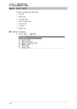
See "
Sensor Test" in "4.3.8 SELF
TEST".
Communication Lines
See "
Line Test" in "4.3.8 SELF TEST".
Memory
See "
Memory Test" in "4.3.8 SELF
TEST".
Panel
See "
Key Test" in "4.3.8 SELF TEST".
Checking the Monitor
See "
Monitor Display Test" in "4.3.8
SELF TEST".
Magnetron Current
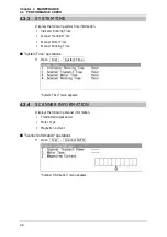
See "4.3.4 SCANNER INFORMATION".
Error Logging Display
See 4.3.6 ERROR LOG.
System Information Display
See 4.3.2 SYSTEM INFORMATION and
4.3.3 SYSTEM TIME.
Summary of Contents for JMA-3300 Series
Page 2: ......
Page 16: ...WARNING LABEL MOUNTING POINT xiv NCD 2182 Display Unit ...
Page 17: ...WARNING LABEL MOUNTING POINT xv NBA 5111 Power Supply NBD 865 Rectifier unit ...
Page 30: ...GLOSSARY xxviii ...
Page 46: ...Chapter 1 GENERAL AND EQUIPMENT COMPOSITION 1 5 GENERAL SYSTEM DIAGRAMS 1 16 ...
Page 244: ...Chapter 4 MAINTENANCE 4 6 TROUBLE SHOOTING 4 36 ...
Page 266: ...APPENDIX APPENDIX 2 Fig A2 NKE 2043 SCANNER INTERCONNECTION DIAGRAM ...
Page 268: ...APPENDIX APPENDIX 4 Fig A4 NKE 2062HS SCANNER INTERCONNECTION DIAGRAM ...
Page 271: ...APPENDIX APPENDIX 7 APPENDIX INSTRUCTION MANUAL LJ 1 6 6 11 5 17 5 211 7 21 5 0 ...
Page 272: ...APPENDIX APPENDIX 8 Fig A8 NKE 2063AHS SCANNER INTERCONNECTION DIAGRAM ...
Page 274: ...APPENDIX APPENDIX Fig A NCD 2182 DISPLAY UNIT INTERCONNECTION DIAGRAM ...
Page 276: ...APPENDIX APPENDIX 1 Fig A1 JMA 3314 INTERCONNECTION DIAGRAM ...
Page 277: ...APPENDIX APPENDIX 1 APPENDIX INSTRUCTION MANUAL Fig A1 JMA 3334 INTERCONNECTION DIAGRAM ...
Page 278: ...APPENDIX APPENDIX 1 Fig A1 JMA 3316 HS INTERCONNECTION DIAGRAM ...
Page 280: ...APPENDIX APPENDIX 1 Fig A1 JMA 3340 4 4HS 6 6HS INTERCONNECTION DIAGRAM ...
Page 297: ......


