Chapter 2
OPERATIONS
2.2
PANEL
2-2
2.2
PANEL
Operate this equipment with the panel of the Display unit.
No.
Key
Description
ձ
MENU
Press:
Opens/closes the menu.
Hold down: Opens the code input screen (the Adjust Menu).
ղ
CLEAR
Press:
Cancels menu operations.
Returns to upper menu.
Stops the alarm sound.
ճ
ENT
Press:
Enters the selected menu item.
Cursor keys
Press:
Selects menu items. Moves the cursor.
Hold down: Accelerates cursor movement.
մ
GAIN
Press:
Performs the user key 1 function.
Hold down: Switches the sensitivity between manual and automatic
modes.
Turn:
Adjusts receiving sensitivity.
յ
SEA
Press:
Performs the user key 2 function.
Hold down: Switches the sea clutter suppression function between
manual and automatic modes.
Turn:
Removes sea clutter.
ն
RAIN
Press:
Performs the user key 3 function.
Hold down: Switches the rain/snow clutter suppression function
between manual and automatic modes.
Turn:
Removes rain/snow clutter.
շ
RANGE
Press:
Switches the range.
ո
FUNC
Press:
Switches function settings.
Hold down: Opens the function setting menu.
չ
BRILL
Press:
Changes the display brilliance
Hold down: Opens the display color menu.
պ
MULTI
Press:
Opens the soft key menu.
Turn:
Adjusts the selected mode. Changes the setting values.
Selects soft key menu items.
ջ
USB MEMORY
Saves files. Updates the software.
ռ
STBY
Press:
Turns on this equipment (when it is turned off).
Turns to standby state (when the equipment is
transmitting).
Press multiple keys:
Turns off the equipment when pressed together with the
TX/PRF key.
ս
TX/PRF
Press:
Starts transmitting (in standby state)
Tunes the repetition frequency (when transmitting).
Hold down: Turns off the heading line. (after preheating finished).
վ
Soft keys
Press:
Opens the soft key menu.
Summary of Contents for JMA-3300 Series
Page 2: ......
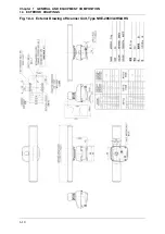
Page 16: ...WARNING LABEL MOUNTING POINT xiv NCD 2182 Display Unit ...
Page 17: ...WARNING LABEL MOUNTING POINT xv NBA 5111 Power Supply NBD 865 Rectifier unit ...
Page 30: ...GLOSSARY xxviii ...
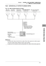
Page 46: ...Chapter 1 GENERAL AND EQUIPMENT COMPOSITION 1 5 GENERAL SYSTEM DIAGRAMS 1 16 ...
Page 244: ...Chapter 4 MAINTENANCE 4 6 TROUBLE SHOOTING 4 36 ...
Page 266: ...APPENDIX APPENDIX 2 Fig A2 NKE 2043 SCANNER INTERCONNECTION DIAGRAM ...
Page 268: ...APPENDIX APPENDIX 4 Fig A4 NKE 2062HS SCANNER INTERCONNECTION DIAGRAM ...
Page 271: ...APPENDIX APPENDIX 7 APPENDIX INSTRUCTION MANUAL LJ 1 6 6 11 5 17 5 211 7 21 5 0 ...
Page 272: ...APPENDIX APPENDIX 8 Fig A8 NKE 2063AHS SCANNER INTERCONNECTION DIAGRAM ...
Page 274: ...APPENDIX APPENDIX Fig A NCD 2182 DISPLAY UNIT INTERCONNECTION DIAGRAM ...
Page 276: ...APPENDIX APPENDIX 1 Fig A1 JMA 3314 INTERCONNECTION DIAGRAM ...
Page 277: ...APPENDIX APPENDIX 1 APPENDIX INSTRUCTION MANUAL Fig A1 JMA 3334 INTERCONNECTION DIAGRAM ...
Page 278: ...APPENDIX APPENDIX 1 Fig A1 JMA 3316 HS INTERCONNECTION DIAGRAM ...
Page 280: ...APPENDIX APPENDIX 1 Fig A1 JMA 3340 4 4HS 6 6HS INTERCONNECTION DIAGRAM ...
Page 297: ......


