Chapter 5 VARIOUS FUNCTIONS
107
5.24.7 TARGET NUMBER ALLOCATION
The start number of targets can be specified for the target symbol or AIS symbol. Use the cross key or the
MULTI control to change the value.
The start numbers of TT and AIS target can be specified respectively.
The start number of TT can be set between 0 and 70.
The start number of AIS can be set between 100 and 900.
5.24.8 TLL TARGET NUMBER ALLOCATION
Select the position that it output as the position of the TLL sentence. The position can be selected from own
ship’s position or the cursor position.
The target number for TLL sentence can be specified.
5.24.9 ALR ALARM FROM AIS
Set the display of NMEA ALR sentence received from AIS.
5.24.10 AIS DISPLAY TARGET
Set the number of AIS display targets. Set this to get a better look at the screen by limiting the number of AIS
symbols.
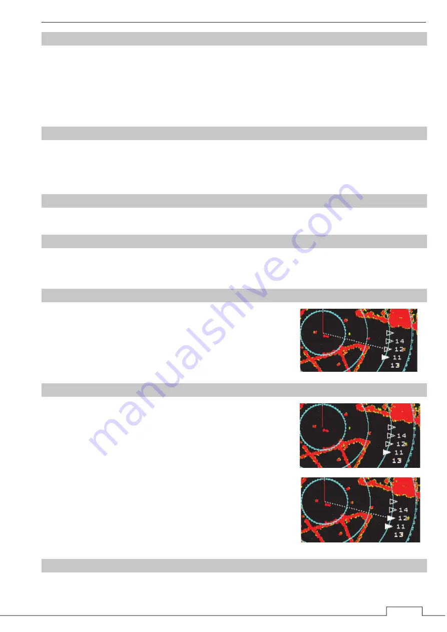
5.24.11 AIS DESTINATION SHIP
Set the MMSI of the AIS destination ship.
Use the cross key or the MULTI control to change the value.
The AIS destination ship is connected ownship with straight dotted line.
If unsetting the AIS destination ship, input “0.”
5.24.12 AIS RETRIEVED VESSEL
Set the MMSI of the AIS retrieved vessel.
Use the cross key or the MULTI control to change the value.
AIS retrieved vessel can be set up to 10 vessels.
The AIS symbol that is set AIS retrieved vessel is filled.
If unsetting the AIS retrieved vessel, input “0.”
Hint: You can set AIS destination ship and retrieved vessel
at the same time. The AIS symbol become to fill and
connect with straight line.
5.24.13 AIS FILTER
Set the range of AIS filter. Use the cross key or the MULTI control to change the value.
Summary of Contents for JMA-3400 Series
Page 2: ......
Page 23: ...WARNING LABEL MOUNTING POINT xxi NKE 2103 4 4HS 6 6HS SCANNER UNIT NCD 2364 DISPLAY UNIT ...
Page 31: ...EQUIPMENT APPEARANCE xxix NKE 2043 SCANNER UNIT NKE 2063A AHS SCANNER UNIT ...
Page 32: ...EQUIPMENT APPEARANCE xxx NKE 2103 4 4HS 6 6HS SCANNER UNIT ...
Page 34: ...EQUIPMENT APPEARANCE xxxii Fuse ...
Page 48: ......
Page 51: ...Chapter 1 INSTALLATION 3 1 2 3 DIMENSIONAL DRAWING OF DISPLAY MOUNTING ...
Page 56: ...Chapter 1 INSTALLATION 8 FLUSH MOUNTING TEMPLATE Note Please note the paper size ...
Page 85: ...Chapter 2 THE BASIC OPERATION 37 2 2 OPERATION UNIT ࢫࣆ ձ ղ ճ մ յ ն շ ո չ պ վ տ ւ ջ ռ ս ր ց ...
Page 266: ...Chapter 13 SPECIFICATIONS 218 13 1 SCANNER DIMENSION 13 1 1 NKE 2043 ...
Page 270: ...Chapter 13 SPECIFICATIONS 222 13 2 DISPLAY DIMENSION 13 2 1 NCD 2364 ...
Page 283: ...235 Chapter 13 SPECIFICATIONS MEMO ...
Page 293: ...APPENDIX A 10 MEMO ...
Page 313: ......


