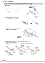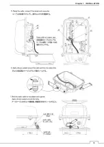
Chapter 1 INSTALLATION
21
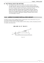
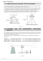
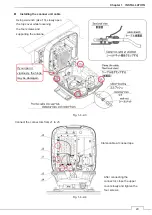
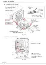
Precautions for transporting and storing the scanner
y
A scanner is a heavy load. Be very careful about handling it.
y
Do not allow the scanner fall on its side while it is stored or being installed.
y
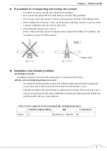
Do not apply rope to the scanner in the way that squeezes or deforms the radiating section.
y
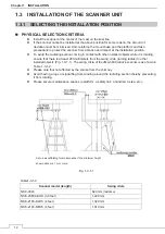
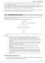
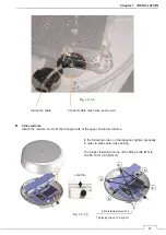
When hoisting the scanner by a crane, do not hoist it by attaching a belt or a rope only to the
scanner's radiating section as shown in Fig1-3-6-9.
y
When lifting the scanner (Fig 1-3-6-10) :
Wrap a cloth around the scanner's support section located at the bottom of the radiator, and
then attach a belt to it to lift the scanner.
Fig 1-3-6-9 Fig 1-3-6-10
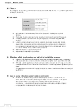
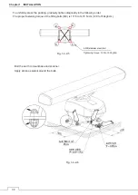
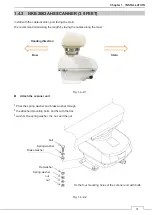
Installation and clamping method
Ŷ
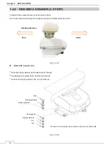
Installation direction
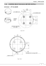
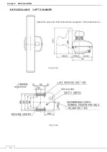
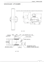
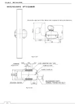
Installation should be done so that the cable gland is oriented toward the stern.
Ŷ
Bolts, nuts and tightening torque to be used
y
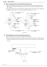
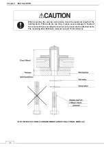
Use stainless steel bolts for the scanner and uniformly tighten all of the bolts using double
nuts for each bolt so that the scanner will not become loose (Table 1-3-6-1).
y
Although the length of the bolt will differ according to the thickness of the mount base, use a
bolt long enough so that more than 4 millimeters of thread protrudes beyond the double nuts
after the double nuts have been tightened.
Table 1-3-6-1 Length of scanner mounting bolts and tightening torque
Thickness of Mount Base
Bolt
Torque (N-m)
X band
12
M10×55 (mm) SUS304
40
Wrap a cloth
OK
㸟
Summary of Contents for JMA-3400 Series
Page 2: ......
Page 23: ...WARNING LABEL MOUNTING POINT xxi NKE 2103 4 4HS 6 6HS SCANNER UNIT NCD 2364 DISPLAY UNIT ...
Page 31: ...EQUIPMENT APPEARANCE xxix NKE 2043 SCANNER UNIT NKE 2063A AHS SCANNER UNIT ...
Page 32: ...EQUIPMENT APPEARANCE xxx NKE 2103 4 4HS 6 6HS SCANNER UNIT ...
Page 34: ...EQUIPMENT APPEARANCE xxxii Fuse ...
Page 48: ......
Page 51: ...Chapter 1 INSTALLATION 3 1 2 3 DIMENSIONAL DRAWING OF DISPLAY MOUNTING ...
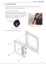
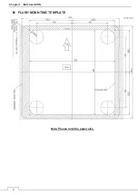
Page 56: ...Chapter 1 INSTALLATION 8 FLUSH MOUNTING TEMPLATE Note Please note the paper size ...
Page 85: ...Chapter 2 THE BASIC OPERATION 37 2 2 OPERATION UNIT ࢫࣆ ձ ղ ճ մ յ ն շ ո չ պ վ տ ւ ջ ռ ս ր ց ...
Page 266: ...Chapter 13 SPECIFICATIONS 218 13 1 SCANNER DIMENSION 13 1 1 NKE 2043 ...
Page 270: ...Chapter 13 SPECIFICATIONS 222 13 2 DISPLAY DIMENSION 13 2 1 NCD 2364 ...
Page 283: ...235 Chapter 13 SPECIFICATIONS MEMO ...
Page 293: ...APPENDIX A 10 MEMO ...
Page 313: ......

