background image

30

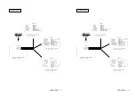
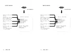
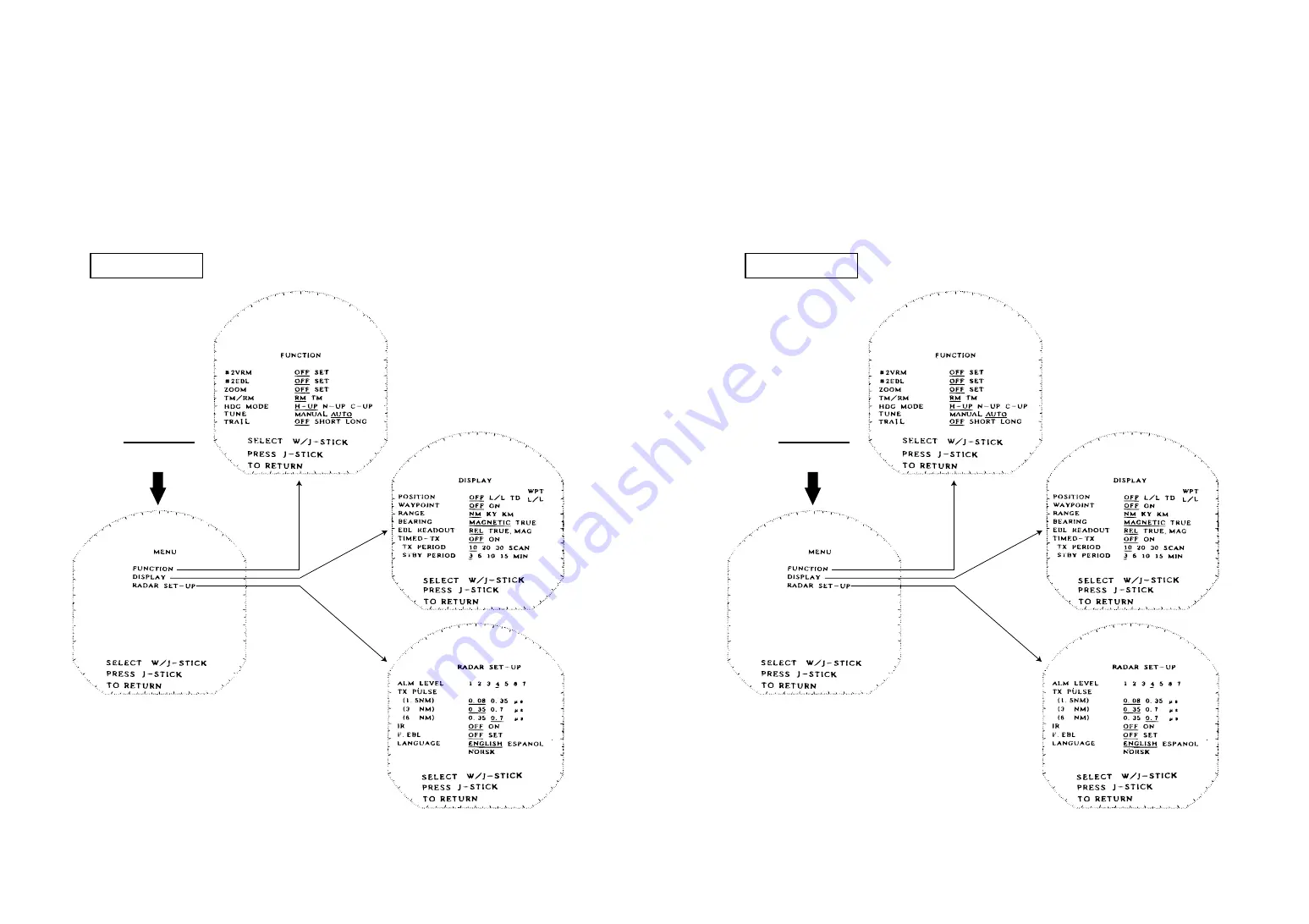
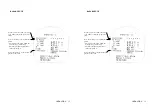
4.27 OPERATING MENU

Press the JOYSTICK (MENU/ENT), and the first menu sheet will be appear.

The JOYSTICK is used to select a particular menu. The particular menu will be

highlighted character.

Pressing the JOYSTICK (MENU/ENT) again will return the display to the nor-

mal video presentation.

MENU

ENT

English Menus

OPERATION

Summary of Contents for Radar 3000

Page 1: ......

Page 2: ...the equipment Equipment damage precaution to alert you of possible harm and or failure of equipment I Thank you for purchasing the RADAR 3000 radar It will provide many years of trouble free use when...

Page 3: ...radar unit should not be relied upon as a substitute for such prudence and judgment CAUTION WARNING II Operating Precautions To avoid electrical shock never touch the inside of the scanner or display...

Page 4: ...III SCANNER UNIT NKE 1046 DISPLAY UNIT NCD 3744 Equipment Photograph III SCANNER UNIT NKE 1046 DISPLAY UNIT NCD 3744 Equipment Photograph...

Page 5: ...4 9 SETTING DIMMER 23 4 10 SETTING OFFSENT 24 4 11 RANGE MEASUREMENT 24 4 12 BEARING MEASUREMENT 25 IV Table of Contents Symbol Used In This Manual I Operating Precautions II Equipment Photograph III...

Page 6: ...SCANNER UNIT 44 8 3 DISPLAY UNIT 44 APPENDIX Fig 1 RADAR 3000 SCANNER UNIT NKE 1046 RADOME TEMPLATE V 4 13 SETTING GUARD 26 4 14 RINGS 27 4 15 SHM 27 4 16 POSITION 27 4 17 WAYPOINT 27 4 18 READ OUT DI...

Page 7: ...erence TI Trigger VD Video VOM Volt Ohm Meter VRM Variable Range Marker WPT Waypoint X MIT Transmit VI Radar Glossary of Terms The following is a list of abbreviations and acronyms which may be used i...

Page 8: ...ction Trail indication Man overboard indication Intermittent transmission INTRODUCTION INTRODUCTION 1 SECTION 1 1 1 FUNCTION The JRC RADAR 3000 Radar is compact raster scan radar with a 4 kW trans mit...

Page 9: ...th NMEA Sun Cover MTV301855 Scanner Mounting Hardware MPXP31711 Display Mounting Hardware MPTG02024 2 1 3 COMPONENTS Table 1 1 indicates a listing of items that are included with your new radar system...

Page 10: ...IG 1 2 SCANNER MOUNTING DIMENSION FIG 1 1 DISPLAY MOUNTING DIMENSIONS 1 4 CONSTRUCTION INTRODUCTION 3 FIG 1 2 SCANNER MOUNTING DIMENSION FIG 1 1 DISPLAY MOUNTING DIMENSIONS 1 4 CONSTRUCTION INTRODUCTI...

Page 11: ...CENT Key SHM RINGS Key Brilliance Dimmer Key MOB Key Transmit off Key Stand by off Key DISPLAY UNIT 4 OPERATING CONTROLS AND FUNCTIONS SECTION 2 OPERATINGCONTROLSANDFUNCTIONS FIG 2 1 OPERATING CONTROL...

Page 12: ...CK and I or O operation I In mode alarm O Out mode alarm Blank OFF OPERATING CONTROLS AND FUNCTIONS 5 2 1 CONTROL PANEL Stand by off Key Turn ON power to Display and Scanner and activates 90 second co...

Page 13: ...ed Range Up Down key Increases or decreases the range scale in use OPERATING CONTROLS AND FUNCTIONS 6 EXP Key Target Expander ON OFF OFFSET Key Places origin at any point on screen up to 2 3 radius In...

Page 14: ...general system diagram for the RADAR 3000 is shown on the following page INSTALLATION INSTALLATION 7 SECTION 3 This section provides practical guidelines to assist in the planning and installa tion o...

Page 15: ...8 INSTALLATION FIG 3 1 GENERAL SYSTEM DIAGRAM 8 INSTALLATION FIG 3 1 GENERAL SYSTEM DIAGRAM...

Page 16: ...FIG 3 1 and 3 2 as a guide install the display unit and secure to the mounting surface INSTALLATION 9 3 3 MOUNTING THE DISPLAY UNIT When planning the installation for your display unit the following c...

Page 17: ...10 FIG 3 3 SCANNER MOUNTING DIMENSION INSTALLATION FIG 3 2 DISPLAY MOUNTING DIMENSIONS 10 FIG 3 3 SCANNER MOUNTING DIMENSION INSTALLATION FIG 3 2 DISPLAY MOUNTING DIMENSIONS...

Page 18: ...d Tighten the ground terminal and securing the clamping plate with the rub ber grommet INSTALLATION 11 3 4 MOUNTING THE SCANNER UNIT Selecting an adequate location for the scanner unit requires carefu...

Page 19: ...connector In case of different pin assignment the RADAR 3000 or con nected NAV AID will be damaged 12 CAUTION INSTALLATION 3 6 ELECTRICAL CONNECTION 3 6 1 DC POWER CABLE The RADAR 3000 will work with...

Page 20: ...COMPASS Data Ground 1 2 6 5 4 3 View show wire end of Cable Plug Socket FIG 3 5 EXTERNAL INTERFACE 13 INSTALLATION The RADAR 3000 will interface with any NAV AID GPS or LORAN and compass that has the...

Page 21: ...PUR COAX Coax 50 ohms SHIELDED WIRE LARGE WIRE SMALL WIRE NKE 1046 SCANNER UNIT P1 CFQ8026 10 15 20 14 FIG 3 6 INTERCONNECTION DIAGRAM INSTALLATION NCD 3744 DISPLAY UNIT 1 2 3 DC DC P401 WHT BLK 1 2 3...

Page 22: ...elect BEARING by using the JOYSTICK press the JOYSTICK for the bearing adjustment mode INSTALLATION 15 3 7 INITIAL OPERATION AND CHECK OUT 3 7 1 INSPECTION AFTER THE INSTALLATION After completing the...

Page 23: ...m the following steps PUSHING DISPLAY TIMING EARLY CORRECT PULLING DISPLAY TIMING LATE INSTALLATION 16 Put the EBL over the desired target using the J DIAL and press the JOY STICK Move the EBL so that...

Page 24: ...ADJUST MODE MIN MAX MIN MAX MIN MAX TUNE PRESET ADJUST MODE ADJUST WITH J DIAL PRESS J STICK TO END 17 Set the range scale to 3 NM Set the gain control to desired level Set the SEA RAIN and IR to Off...

Page 25: ...buzzer sound level using the J DIAL Press the JOYSTICK to end the buzzer setting mode INSTALLATION 18 3 7 7 BUZZER VOLUME At the time of shipment the Buzzer sound has been set to maximum position Whe...

Page 26: ...CENT Key SHM RINGS Key Brilliance Dimmer Key MOB Key Transmit off Key Stand by off Key DISPLAY UNIT 19 SECTION 4 Generally the operation of the RADAR 3000 is easy straight forward However the navigato...

Page 27: ...s the X MIT OFF key OPERATION PUSH XMIT TO OPERATE 1 30 V1 0 0000 HRS FIG 4 2 TURN ON OFF THE RADAR 20 4 2 TURNING THE RADAR ON AND OFF TO TURN ON Press the STBY OFF key TO TRANSMIT Press the X MIT OF...

Page 28: ...he out side of NAV AID COMPASS As for the connection with NAV AID COMPASS look at the 3 6 2 chapter 21 FIG 4 3 LAYOUT OF THE SCREEN OPERATION INTERFERENCE REJECTION ON TARGET EXPANDER ON RING INTERVAL...

Page 29: ...le or higher Minor readjustment may be necessary after the radar has warmed up 10 minutes OPERATION 22 4 3 SELECTING A RANGE The actual range scale and range rings interval is shown in the upper left...

Page 30: ...terate all clutter since this setting could prevent the detection of close in target echoes CAUTION 23 4 6 REDUCING SEA CLUTTER The sea clutter control is normally used on the shorter ranges to suppre...

Page 31: ...VRM SET then press the JOYSTICK The VRM2 appears highlight on the upper right corner of the display 24 4 10 SETTING OFFCENT By pressing the OFFCENT key the display is into off center mode by 2 3 ra di...

Page 32: ...ighlighted 3 Using 2 EBL Press the JOYSTICK Selects FUNCTION menu then press the JOYSTICK OPERATION 25 Rotate the J DIAL clockwise for outer direction or counterclockwise for inner direction to move t...

Page 33: ...into highlight at IN mode alarm At this time the zone will have been memorized for use at any time 26 OPERATION Selects 2 EBL SET then press the JOYSTICK The EBL2 appears high light on the upper righ...

Page 34: ...want to change to an OUT mode alarm press the GUARD key START POINT GUARD ZONE WIDTH BEARING LIMITS 27 OPERATION 4 14 RINGS Press the SHM RINGS key to set rings on off 4 15 SHM Momentarily disables th...

Page 35: ...OPERATION If you ll watch the RADAR BEACON and the SART set the pro cess as follows IR OFF CAUTION 28 4 18 READ OUT DIMENSION OF BEARING This selects the bearing for heading flush EBL cursor and wayp...

Page 36: ...SET UP menu Select desired language Press the JOYSTICK to exit the language setting mode OPERATION 29 4 23 TIMED TX MODE The TIMED TX mode allows the operator to program the radar to automati cally t...

Page 37: ...NT again will return the display to the nor mal video presentation MENU ENT English Menus OPERATION 30 4 27 OPERATING MENU Press the JOYSTICK MENU ENT and the first menu sheet will be appear The JOYST...

Page 38: ...31 OPERATION MENU ENT Spanish Menus 31 OPERATION MENU ENT Spanish Menus...

Page 39: ...32 OPERATION MENU ENT Norwegian Menus 32 OPERATION MENU ENT Norwegian Menus...

Page 40: ...er glow lasts approx 15 to 16 seconds and a long after glow lasts approx 1 minutes 62 to 63 seconds 33 OPERATION Menu Item Description FUNCTION Selects 2VRM Selects 2EBL Doubles the size of the image...

Page 41: ...es the standby sleep time Functions identified by an require an optional unit or an external device 34 OPERATION DISPLAY Displays the position of the own ship or waypoint in terms of latitude and long...

Page 42: ...lse width the bet ter the sensitivity is Selects the language for the text dis played on the screen 35 OPERATION RADAR SET UP Sets the guard zone alarm sensitivi ty in terms of intensity of the echo i...

Page 43: ...e sea clutter Adjusts the volume of the alarm buzzer The volume must normally be set to its maximum 36 OPERATION INITIAL SETTING MENU ENT LONG PRESS Adjusts the bearing on the PPI screen Adjusts the r...

Page 44: ...ny stranding and so on Need to retune the set for normal operation on completeion Attention EXAMPLE 37 OPERATION SART Code Position of SART Other Ships Land Position of the Rescue Craft 4 28 DISPLAY O...

Page 45: ...nance inspect the radar system for the follow ing points 1 Check all hardware for tightness WARNING 38 MAINTENANCE SECTION 5 The purpose of this section is to provide servicing instructions for the se...

Page 46: ...e a problem When using it wipe softly never rub the screen surface with excessive force MAINTENANCE 39 2 Check for evidence of any corrosion of the scanner unit display unit or its cable and connector...

Page 47: ...the dealer you purchased the product our sales department or your nearest branch or business office 40 SECTION 6 AFTER SALES SERVICE AFTER SALES SERVICE When asking for repair When a system failure is...

Page 48: ...ES NO 14 LOG speed can be normally displayed YES NO 15 Others Error message etc AFTER SALES SERVICE 41 RADAR FAILURE CHECKLIST When ordering for repair check the following items fill in the sheet and...

Page 49: ...ans Other wise short circuiting may occur resulting in heat generation bursting or ignition WARNING 42 7 1 EQUIPMENT DISPOSAL Dispose of this equipment by following the ordinances or regulations of th...

Page 50: ...10 Power consumption Approx 65 W 11 AVR Floating AVR system SPECIFICATIONS SECTION 8 SPECIFICATIONS 43 8 1 GENERAL 1 Maximum range 24 NM 2 Minimum range Less than 25 m on the 0 125 NM range 3 Range sc...

Page 51: ...l 6 Bearing scale 360 scale graduated at intervals of 1 7 VRM 3 digit readout 8 EBL 3 digit readout 44 SPECIFICATIONS 8 2 SCANNER UNIT 1 Dimensions Diameter 620 mm Height 275 mm 2 Mass Approx 9 5 kg 3...

Page 52: ...83 RMA RMB RMC GLL GTD VTG BWC sentence Compass NMEA0183 HDM HDT VHW or HSC sentence SPECIFICATIONS 45 9 Alarm Audible alarm with zone mark 10 Off Center 2 3 radius 11 Planned TX Rotation period 10 20...

Page 53: ...forword aft BREATHING TUBE 0 591 15mm 1 14 29mm 4 0 47 12mm 5 9 16 141 7mm 3 149 80mm CABLE ACCESS 4 330 110mm 5 9 16 141 7mm Fig 1 RADAR 3000 SCANNER UNIT NKE 1046 RADOME TEMPLATE...

Page 54: ...ng Bldg 84 18 4 GA Chungang Dong Chung Ku Pusan KOREA Phone 82 51 441 0035 Fax 82 51 464 0695 01 05 Main Office Plants Main Office Akasaka Twin Tower Main 17 22 Akasaka 2 chome Minato ku Tokyo 107 843...

Page 55: ......
Reviews: