675
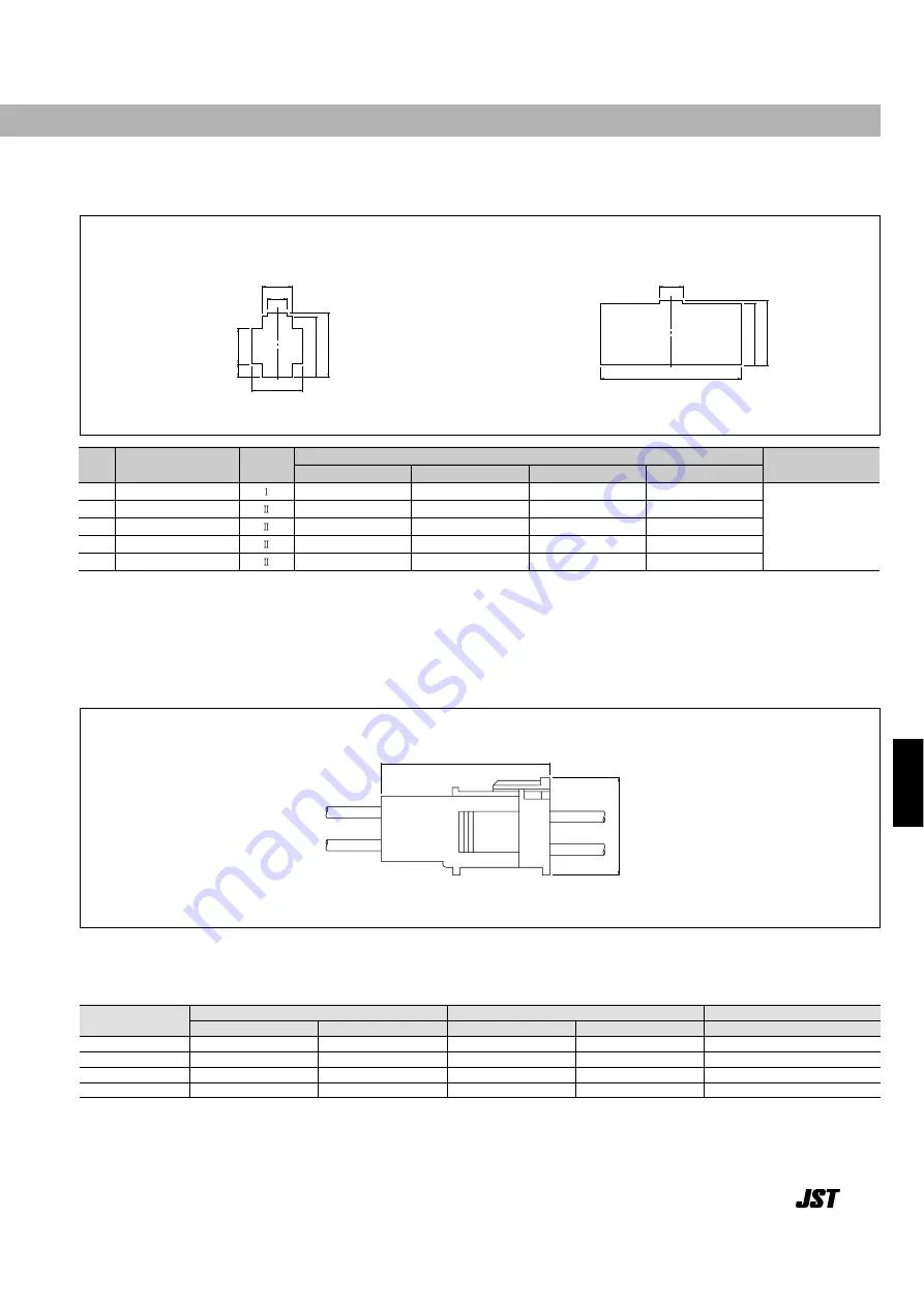
Panel layout––––––––––––––––––––––––––––––––––––––––––––––––––––––––––––––
Shape l
Shape ll
Note:
1. Punch holes in the panel according to the sketch and table shown above. Burrs must be removed.
2. The strength of the panel must be considered when punching two or more holes.
3. The connector must be inserted from the same side as the hole is punched.
6.5
(.256)
B
7.8
(.307)
2.7
(.106)
A
D
C
B
D
C
A
Cir-
cuits
Receptacle
housing
Panel dimensions mm(in.) General tolerance
±
0.13(
±
.005)
A
B
C
D
Applicable panel
thickness mm(in.)
Panel
hole
shape
2
4
8
12
16
XLR-02V
XLR-04V
XLR-08V
XLR-12V
XLR-16V
11.5( .453)
16.5( .650)
26.5(1.043)
36.5(1.437)
46.5(1.831)
4.4(.173)
5.2(.205)
5.2(.205)
5.2(.205)
5.2(.205)
13.95(.549)
13.95(.549)
13.95(.549)
13.95(.549)
13.95(.549)
13.2(.520)
13.2(.520)
13.2(.520)
13.2(.520)
13.2(.520)
0.7 to 2.4
(.028 to .094)
Assembly layout––––––––––––––––––––––––––––––––––––––––––––––––––––––––––
30.9(1.217)
17.7(.697)
XL
CONNECTOR
Contact
Crimp applicator MKS-L
Compact crimp applicator MKS-LS
Strip-crimp applicator MKS-SC
with safety cover
without safety cover
with safety cover
without safety cover
with safety cover
Applicator for the semi-automatic press AP-K2N –––––––––––––––––––––––––––––––
SXF-01T-P0.7
APLMK SXF01-07
APLNC SXF01-07
–
–
–
SXF-41T-P0.7
APLMK SXF41-07
APLNC SXF41-07
–
–
APLSC SXF41-07
SYM-01T-P0.7
APLMK SYM01-07
APLNC SYM01-07
–
–
–
SYM-41T-P0.7
APLMK SYM41-07
APLNC SYM41-07
–
–
–


