background image

WIRELESS MICROPHONE SYSTEM

1

1. Important Caution

2. Features

• 

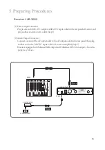
Always make all connections before plugging the unit into an AC power outlet. 

• 

Do not leave the devices in a place neither with high temperature nor high humidity.

• 

Always do not handle the power cord with wet hands !

• 

Keep the devices away from fire and heat sources. 

• 

Due to the PLL synthesized technology, the system can offer up to 1441 selectable frequencies 

for choosing simultaneously.

• 

6 groups, maximum 23 channels in one group.

• 

The true diversity reception with 2 independent RF receivers ensure the stable transmission and 

reception.

• 

Adjustable Pilot tone squelch control can effectively reduce the noise. 

• 

Equipped with S.A.W. filter benefits the interference-resistant. 

• 

Tuned antennas can benefit the stable RF reception.

• 

Built-in Noise Squelch circuity & Mute function are available to restrain the interference for 

signals.  

• 

Rugged metal housing can pass through the difficult environment. 

• 

Equipped with balanced XLR and balanced output allow great convenience.

• 

Anti-interference design is available to work with every computer device.

• 

Transmission power selectable between 

“High”

and 

“Low”


Summary of Contents for Mh-36G2

Page 1: ...US 36G2 Mh 36G2 PT 36BG2 59508 043 03 No 148 Gongye 9th Rd Dali Dist Taichung City 41280 Taiwan R O C Tel 886 4 24938803 Fax 886 4 24914890 Email jts jts com tw PROFESSIONAL CO LTD www jts com tw ...

Page 2: ...InstructionManual UHF PLL TRue DIversity WIRELESS SYSTEMS Mh 36G2 PT 36BG2 US 36G2 ...

Page 3: ...Thank you for choosing the JTS wireless system In order to obtain the best efficiency from the system you are recommended to take few minutes to read this instruction manual carefully ...

Page 4: ...6BG2 3 4 Optional Condenser Microphone 4 Part Identification Accessories 4 1 Receiver US 36G2 4 2 Handheld Transmitter Mh 36G2 4 3 Body pack Transmitter PT 36BG2 4 4 Optional Condenser Microphone 4 5 Accessories 5 Preparing Procedures 6 Basic Operation 7 Recommendation 8 Important notice 1 1 2 2 2 3 3 6 6 7 8 9 13 14 15 28 28 INDEX ...

Page 5: ...nels in one group The true diversity reception with 2 independent RF receivers ensure the stable transmission and reception Adjustable Pilot tone squelch control can effectively reduce the noise Equipped with S A W filter benefits the interference resistant Tuned antennas can benefit the stable RF reception Built in Noise Squelch circuity Mute function are available to restrain the interference fo...

Page 6: ... Power On Off Group Channel Frequency Up Down Frequency Scan Audio Level Lock on Output Pad 12dB 12dB 600Ω Pilot Tone Noise Mute 12V 500mA 1 XLR Balanced Socket 1 Ø6 3mm Unbalanced phone jack 212 3mm W 38 3mm H 144mm D Frequency Preparation Carrier Frequency Range RF Outputs Stability Frequency Deviation LCD Display Controls Spurious Emissions Audio Frequency Response Battery PLL Synthesized Contr...

Page 7: ...60 3 dB 2 2kΩ 130dB Ø5mm W 9mm H 20 7g CM 125i 201C4 4P Mini XLR 201C3 3P Mini XLR 201CS 3 5 stereo plug 201CR 50 18 000 Hz Omni directional 53 3 dB 4 4kΩ 130dB Ø4mm W 11mm H 7g cable excluded Lavaliere Microphone Frequency Preparation Carrier Frequency Range RF Outputs Stability Frequency Deviation LCD Display Controls Output connector Spurious Emissions Audio Frequency Response Battery PLL Synth...

Page 8: ...z Cardioid 68 3 dB 680Ω 130dB 285mm W 55mm H 111 3mm D 56 3g Model No Connector Option Connector Frequency Response Polar Pattern Sensitivity at 1000Hz Impedance Max SPL for 1 THD Dimension mm Net Weight CM 214i 801C4 4P Mini XLR 801C3 3P Mini XLR 801CS 3 5 stereo plug 801CR 60 15 000 Hz Omni directional 60 3 dB 1 8kΩ 130dB 125mm W 134mm H 157mm D 32 9g CM 214Ui 4P Mini XLR 30 18 000 Hz Cardioid 6...

Page 9: ...dB Model No Connector Frequency Response Polar Pattern Sensitivity at 1000Hz Impedance Max SPL for 1 THD Good For Model No Connector Frequency Response Polar Pattern Sensitivity at 1000Hz Impedance Max SPL for 1 THD Good For CX 500 4P Mini XLR 20 20 000 Hz Omni directional 58 3dB 1 5kΩ 130 dB Violin CX 508W 4P Mini XLR 50 18 000 Hz Cardioid 67 3 dB 220Ω 130 dB Winds CX 500F 4P Mini XLR 20 20 000 H...

Page 10: ...LCD Display Volume control AF signal level RF signal level Antenna DC socket for connection of main unit AF output jack socket AF UNBAL Balanced XLR socket Antenna input socket 1 4 7 10 11 12 13 2 5 8 3 6 9 1 3 4 9 2 8 5 6 7 VOL MIN MAX DIVERSITY RECEIVER US 36G2 ID SQ LOCK ATT ON CH MHz 13 12 10 13 11 500 1856 ...

Page 11: ... G2 Mh 36 G2 Mh 36 MHz MHz Interchangeable capsule LCD display Set button Down button UP button Power On Off switch Mute On Off switch Battery tray button Battery tray 4 2 Handheld Transmitter Mh 36G2 14 17 15 18 20 16 19 21 14 19 15 18 16 17 20 21 ...

Page 12: ...elect the settings of transmitter Down button select the settings of transmitter 4 Pin mini XLR mic input Power Switch Mute Antenna Belt Clip LCD Panel of the Body Pack Transmitter Battery status display battery status Group Channel 32 31 30 29 22 23 25 26 27 28 24 MHz UHF PLLTransmitter POWER MUTE 22 23 30 27 29 25 28 24 26 32 31 ...

Page 13: ...Mini XLR 3 Pin Mini XLR 3 5 Stereo Plug 4Pin Hirose connecter Windscreen 33 35 36 37 38 34 4 4 Optional Condenser Microphone Lavaliere Microphone CM 501 CM 201i CM 125i CM 501 CM 201i CM 125i 38 38 38 33 33 33 34 35 36 37 Option Option Option ...

Page 14: ...band Headband 4 Pin Mini XLR 3 Pin Mini XLR 3 5 Stereo Plug 4Pin Hirose connecter Windscreen 40 42 43 46 44 45 39 41 Standard 4 Pin Mini XLR 3 Pin Mini XLR 3 5 Stereo Plug CM 214i CM 214Ui CM 235i CM 214ULi CX 504 40 40 40 46 46 46 39 39 39 40 41 46 46 39 39 Option Option Option 43 44 42 45 ...

Page 15: ...e Clip Windscreen 4 Pin Mini XLR 3 Pin Mini XLR 3 5 Stereo Plug 4Pin Hirose connecter Ear hook Microphone CM 801 CM 804i CM 8015 CM 825i 52 54 53 55 56 49 51 50 47 48 Option Option Option 48 52 49 51 50 47 52 49 51 50 47 48 52 49 51 50 47 52 49 51 50 47 CM 801 CM 804i CM 8015 CM 825i 54 55 53 56 ...

Page 16: ...lip Bracket Volume Control Windscreen 4 Pin Mini XLR 60 61 62 59 58 57 Compatible Instrument Microphone CX 500 CX 500F CX 520 CX 508W CX 516W CX 508W CX 516W 57 57 58 62 59 61 61 61 61 CX 500F CX 500 57 58 CX 520 60 ...

Page 17: ...Power Supply 220V 60Hz Screwdriver DR 900 Dual Rack Adaptor RM 901 Rack Mount Kit RP 900 Panel Cover AF output cable with Φ6 3 plug at both ends GC 80 GC 100 Guitar Cable GC 80L GC 100L Guitar Cable 4 5 Accessories 66 68 69 70 65 67 64 63 Option Option Option Option Option Option Option A B C 63 65 64 67 66 A B C 68 69 70 ...

Page 18: ...to an AC outlet Step 1 2 Audio Output Connector Connect one end of the AF output cable to the AF output socket in the rear panel then plug another end to the MIC IN input socket of a mixer or amplifier Step 2 Receiver equipped with balanced XLR output and Unbalanced Ø6 3mm output choose the proper way for use MIXER AC DC ADAPTOR AC POWER SOCKET AUDIO OUTPUT DC INPUT 2 1 500 1856 ...

Page 19: ... key to set 2 The Channel flash Press or button to select a desired channel Press SET key to set Number of channels for each group Group 1 Channel 1 21 Group 2 Channel 1 22 Group 3 Channel 1 18 Group 4 Channel 1 21 Group 5 Channel 1 21 Group 6 Channel 1 21 3 Frequency adjusting 3 1 Press down SET button for 3 seconds 3 2 Press SET key twice With the 3 digits of the LCD blinking VOL MIN MAX DIVERSI...

Page 20: ...channel scan The receiver will automatically scan the environment and identify the frequencies that have been occupied and will skip to next available frequency 2 press Sc OFF Turn off the channel scan 3 Press SET key to save the setting SQ CH MHz MUTE GROUP When Sc ON When enter group and channel menu the receiver will start to scan when SCAN display on LCD Receiver will scan every channel in the...

Page 21: ...er represents lower sensitivity Lower number represents higher sensitivity 2 Press SET key to save the setting 6 Attenuate Set audio output level 6 1 Press down SET button for 3 seconds 6 2 Press the SET button several times until the At ON or At OFF is displayed on screen 1 press At ON XLR MIC Output volume is lower than Ø6 3 mm output by 10dB 2 press At OFF XLR MIC Output and Ø6 3mm output volum...

Page 22: ...eral times until the Lo ON or Lo OFF is displayed on screen 1 press Lo ON the receiver panel key functions are locked To unlock press SET button for 3 second Lo ON is displayed on screen Press to unlock 2 press Lo OFF Unlock 3 Press SET key to save the setting LOCK LOCK SQ CH GROUP LOCK LOCK ...

Page 23: ...screen 1 The 3 digits on the left of the LCD blinking press or keys to change the frequency at an increment of 1MHz Press SET key to set 2 The 3 digits on the right of the LCD blinking press or keys to change the frequency at an increment of 0 025MHz Press SET key to set PS keeping the or keys pressed down makes the number change faster 2 3 When setting your desired frequency while a preset channe...

Page 24: ...le the frequency is displayed on screen 1 Press down SET key for 3 seconds 2 The 3 digits on the left of the LCD begin to blink press SET key twice to display the channel on LCD now adjust the channel by the same step of 3 2 the group will flash Point 1 2 4 Sensitivity adjusting 4 1 Press down SET button for 3 second The 3 digits of frequency or channel on the left of the LCD begin to blink 4 2 Pr...

Page 25: ...r 2 Press rF Lo low transmitting power 3 Press SET key to save the setting 6 Setting key lock 6 1 Press down SET button for 3 second The 3 digits of frequency or channel on the left of the LCD begin to blink 6 2 Press the SET button several times until the Loc On or Loc OFF on screen 1 Press Loc On the handheld panel key functions are locked To unlock press SET button for 3 second Loc On begin to ...

Page 26: ...econds 2 2 When frequency is displayed on screen 1 The 3 digits on the left of the LCD blinking press or keys to change the frequency at an increment of 1MHz Press SET key to set 2 The 3 digits on the right of the LCD blinking press or keys to change the fre quency at an increment of 0 025MHz Press SET key to set PS keeping the or keys pressed down makes the number change faster 2 3 When setting y...

Page 27: ... channel while the frequency is displayed on screen 1 Press down SET button for 3 seconds 2 The 3 digits on the left of the LCD begin to blink press SET key twice to display the channel on LCD now adjust the channel by the same step of 3 2 the group will flash Point 1 2 4 Sensitivity adjusting 4 1 Press down SET button for 3 second The 3 digits of frequency or channel on the left of the LCD begin ...

Page 28: ...equency or channel on the left of the LCD begin to blink 6 2 Press the SET button several times until the rFP Hi or rFP Lo on screen 1 Press rFP Hi high transmitting power 2 Press rFP Lo low transmitting power 3 Press SET key to save the setting 7 Setting key lock 7 1 Press down SET button for 3 second The 3 digits of frequency or channel on the left of the LCD begin to blink 7 2 Press the SET but...

Page 29: ...WIRELESS MICROPHONE SYSTEM 25 2 Press Loc OFF 3 Press SET key to save the setting ...

Page 30: ... body pack transmitter 2 Headset microphone Put the headband behind your head and fix the temples on your ears as shows then adjust the gooseneck to have best miking Plug the connector into input socket on the body pack transmitter 3 Instrument Microphones The system is compatible with JTS various instrument microphones For detail please refer to user s manuals of these microphones MIC IN ...

Page 31: ...ear hook by twisting the loop or expanding it Curve and bend the boom to fit your face Attach the detachable cable to a suitable place by a cable clip 2 Lightweight Single Ear Hook Microphone Try on whether the original curve is tight or loose Re try and push the fixed curve against your earlobe Curve and Bend the boom to fit your face Attach the detachable cable to a suitable place by a cable cli...

Page 32: ...e same time with new ones 8 Important Notice 1 JTS offers wireless systems in a selection of bands that conform to the different government regulations of specific nations or geographic regions These regulations help limit radio frequency RF interference among different wireless devices and prevent interference with local public communications channels such as television and emergency broadcasts 2...

Reviews: