background image


- 8 - 

92 

Sensor Spring Wire 


93 

Sensor Wire 


94 

Magnet 


KEY PARTS FOR INSTALLATION 


Summary of Contents for Cyclo-6

Page 1: ...JTX Cyclo 6 ...

Page 2: ... 2 CONTENTS SAFETY GUIDELINES 3 MAINTENANCE GUIDELINES 4 EXPLODED DRAWING 5 PARTS LIST 6 INSTALLATION 8 OPERATION 17 TRAINING GUIDELINES 18 ...

Page 3: ...and water solution To avoid damaging the finish on the bike never use a petroleum based solvent when cleaning 7 Please keep children away from the bike while it is in use Do not allow children to use the bike 8 Do not dismount from the bike until the pedals are at a complete STOP 9 If you have any pain or tightness in your chest an irregular heartbeat shortness of breath feel faint or have any dis...

Page 4: ...arts of crank arms and pedals These parts require correct torque to be maintained over time Use a foot pound torque wrench to maintain 30 35 lbs of pressure on the main crank arms Use a pedal wrench to keep pedals fully tightened 3 Regularly tighten all other nuts and bolts 4 Regularly lubricate all moving parts 5 After your session unscrew the resistance brake so that perspiration on the flywheel...

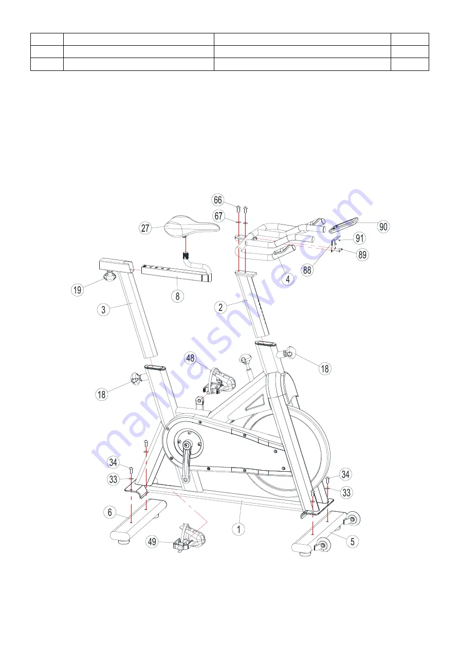
Page 5: ... 5 EXPLODED DRAWING ...

Page 6: ... P1 5 lengthen 2 19 Pop Pin M16 P1 5 1 20 Braking Knob ABS 1 21 Plastic Sheath Inner Pipe 45 45 2 35 35 Square Tube 1 22 Cap of Square tube 35 35 2T Square Tube 1 23 Base Leveler M10 4 24 Pulley φ15 φ71 5 W23 2 25 Plastic Sheath φ19 φ15 5 40L 1 26 Braking Limited Block 20 20 10T 1 27 Seat 1 28 Belt 5PK54 1 29 Rubber Mat 20 20 2T 1 30 Hexagon Nut M5 1 31 Axle Welding φ25 167 5L 1 32 Flywheel Φ460 3...

Page 7: ...15L 12 66 Inner Hexagon Flat Round Screw M10 25 2 67 Flat Φ20 Φ10 1 5 2 68 Inner Hexagon Flat Round Screw M6 12 2 69 Inner Hexagon Flat Round Screw M10 16 4 70 Inner Hexagon Flat Round Screw M8 27L 1 71 Cross Countersink Screw M5 18 2 72 Inner Hexagon Column Screw M6 55L Whole Teeth 2 73 Inner Hexagon hollow Screw Φ8 M6 30 2 74 Nylon Nut M8 3 75 Crank Cover 2 76 Flat φ16 φ8 2T 2 77 Flat Φ25 Φ8 1T ...

Page 8: ... 8 92 Sensor Spring Wire 1 93 Sensor Wire 1 94 Magnet 1 KEY PARTS FOR INSTALLATION ...

Page 9: ...nd Rear Base According to the following figure fix the Front Base 5 and Rear Base 6 to Main Frame 1 respectively with Flat WasherΦ20 Φ10 1 5 33 and Inner Hexagon Flat Round Head Screw M10 25 34 and fasten them by Inner Hexagon tool ...

Page 10: ... Pedal and Right one Refer to the figure below insert the Left Pedal 48 and Right Pedal 49 to the Crank furthermore fix them to the Main Frame with Opening Wrench 15 PLEASE NOTE THE LEFT PEDAL SHOULD BE SCREWED ANTI CLOCKWISE ...

Page 11: ... 11 Step 3 Assemble the Handlebar Post Slacken the Pop Pin 18 and slide the Handlebar Post 2 into the Handlebar Post Housing on the Main Frame 1 then re tighten the Pop Pin 18 ...

Page 12: ... 12 Step 4 Assemble the Handlebar Fix the Handlebar 4 to the Handlebar Post 2 and tighten it with handle M10 25L 66 and Flat Washer Φ20 Φ10 5 1 5 67 ...

Page 13: ... 13 Step 5 Assemble the Seat Post Slacken the Pop Pin 18 and slide the Seat Post 3 into the Seat Post Housing on the Main Frame then screw on the Pop Pin 18 ...

Page 14: ... re tighten the Pop Pin 19 Take out the Seat 27 slacken the Hexagon Nut 81 a little of the Seat to the counter clockwise direction via using an opening wrench then place the Seat onto the Seat Slider 8 then again use the opening wrench to screw down the Hexagon Nut 81 on the Seat to the clockwise direction ...

Page 15: ...5 Step 7 Assemble the Computer Fix the Computer Holder 88 on the Handlebar with Cross Umbrella Screw M6 10L 89 then assemble the Computer 90 with Cross Umbrella Screw M5 10L 91 and connect the sensor wire ...

Page 16: ...to ensure all of them are fully tightened Position the Cyclo 6 on a clear level surface Use the 4 base levelers to position correctly If you need to move the bike please grasp the Handlebar 4 at the very ends to make the Pulley 24 of Front Base stand on the floor Now the bike can be freely wheeled into position ...

Page 17: ... You cannot use this feature if the computer is in operation FUNCTIONS SCAN Scans through all the functions listed below displaying each one for a few seconds RPM Displays the pedaling Rotation Per Minute Cadence The RPM and SPEED will switch to another display every 6 seconds after you have begun cycling SPEED Displays the user s exercise speed TIME Displays the time elapsed or if you have input ...

Page 18: ... and to minimize injuries Warm up for two to five minutes before using the Cyclo 6 Perform activities that raise your heart rate and warm the working muscles Activities may include brisk walking jogging jumping jacks skipping and running on the spot STRETCHING Stretching while your muscles are warm after a proper warm up and again after your strength or aerobic training session is very important M...

Page 19: ... 19 Unit 3 Harbour Way Industrial Estate Shoreham by Sea BN43 5HZ 01273 453855 Email info jtxfitness com Website www jtxfitness com ...

Reviews: