background image

Installation

3.5

Commissioning

Prior to initial commissioning (or to com-

missioning after maintenance work) fill the

installed device with water and vent:

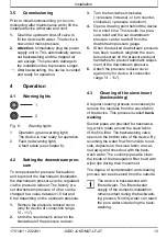
1.

Open the upstream shut-off valve to

fill the device with water. The device is

now under mains pressure.

2. Attention:

 Immediately plug the power

supply unit in. This automatically carries

out backwashing and the trapped air

can escape. This prevents damage to

the installation due to pressure surges.

After backwashing, the device is vented

and ready for operation.

4

Operation

4.1

Warning lights

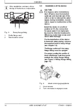
1

2

Fig. 6:

Warning lights

1

Operation (green warning light)

The device is now ready for operation.

2

Fault (red warning light)

A fault exists (see chapter 6).

4.2

Setting the downstream pres-

sure

To compensate for pressure fluctuations

and to protect the downstream installation,

the downstream pressure can be regulated

via the pressure reducer. The factory pre-

set downstream pressure of 4 bar can be

changed to a value between 1.5 bar and

6 bar depending on the upstream pressure:

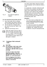
1.

Remove the pressure reducer cover

(only for device of connection range

¾" - 1¼").

2.

Undo the countersunk screw on the

handwheel of the pressure reducer.

3.

Turn the handwheel clockwise

(= pressure increase), or turn counter-

clockwise (= pressure reduction).

4.

Open a drawing point behind the device

for a short time. This results in a pres-

sure relief and the set downstream

pressure can be read off from the

downstream pressure gauge.

5.

When the desired downstream pressure

has been reached, retighten the coun-

tersunk screw on the pressure reducer

handwheel to prevent automatic adjust-

ment of the downstream pressure.

6.

Attach the pressure reducer cover

again (only for device of connection

range ¾" - 1¼").

4.3

Cleaning of the sieve insert

(backwashing)

A regular cleaning process is necessary to

remove the residues from the sieve fabric

of the device. This process is called 

back-

washing

.

Suction pipes are provided for backwash-

ing, which rotate around the sieve fabric

of the fine filter. The backwashing valve

opens on the bottom side of the device. By

reversing the water flow from inside to out-

side, deposits on the sieve fabric are car-

ried away and rinsed out with the back-

wash water. The suction pipes also clean

the inside of the transparent filter bowl with

wiper lips during their movement.
The degree of contamination and cleaning

process can be observed from the outside.

INFO_NO_HEADER

The device is backwashed with

filtered water. The filtered water

supply of the domestic installation

remains intact during the backwash-

ing process. No dirty water can reach

the pure water side during the back-

washing.

1701431 • 2022/01

JUDO JUKOMAT-LF-AT  

13

Summary of Contents for JUKOMAT-LONGLIFE-AT

Page 1: ...Installation and operating instructions JUDO JUKOMAT LONGLIFE AT Automatic domestic water station 2 Valid for EU countries and Switzerland Language English Read before use and store...

Page 2: ...ng even in excerpt form is only per mitted with special approval Dear customers Thank you for the confidence you have shown in us by purchasing this prod uct You have purchased a state of the art devi...

Page 3: ...Warning lights 13 4 2 Setting the downstream pres sure 13 4 3 Cleaning of the sieve insert backwashing 13 4 4 Conversions changes 16 4 5 Battery replacement 16 4 6 Maintenance repair spare parts 17 4...

Page 4: ...plicable national regulations INFO_NO_HEADER Particles that are smaller than the mesh size of the filter supplied and materials causing cloudiness cannot be filtered out of the water 1 2 Application l...

Page 5: ...ec tion e g floor drain in compliance with DIN 1986 must be provided In order to ensure safe drinking water hygiene a free discharge of the waste water acc to DIN EN 1717 must be ensured The pipe must...

Page 6: ...ational use the device must be depressurised If this is ignored the result may be uncon trolled escape of water resulting in water damage to the building home If the device is removed due to an inter...

Page 7: ...ve insert The adhering residues are visible from outside through the transparent filter bowl JUKOMAT LONGLIFE AT 1 The fil ter bowl is visible through the viewing slot of the UV protection screen The...

Page 8: ...el of the pressure reducer 3 Pressure reducer 4 Rotary flange fitting 5 Downstream pressure gauge 6 UV protection screen slideable JUKOMAT LF AT 1 7 Filter bowl 8 Backwashing automatic component 9 Bac...

Page 9: ...ctive filters The device bears the DIN DVGW mark as proof of certification 3 Installation CAUTION The device may only be installed by qualified technical personnel Installation of the device upstream...

Page 10: ...ice Install the device in a vertical position 5 the connection for waste water from backwash ing must be directed downwards Otherwise water may escape and cause water damage For the installation of th...

Page 11: ...giene a free dis charge of the waste water acc to DIN EN 1717 must be ensured Prior to plugging in the device ensure that the wastewater con nection is functional The drain must be large enough so tha...

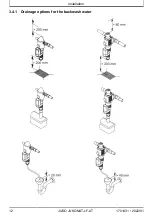
Page 12: ...Installation 3 4 1 Drainage options for the backwash water 12 JUDO JUKOMAT LF AT 1701431 2022 01...

Page 13: ...counter clockwise pressure reduction 4 Open a drawing point behind the device for a short time This results in a pres sure relief and the set downstream pressure can be read off from the downstream pr...

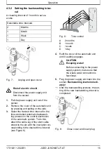
Page 14: ...rding to DIN EN 13443 1 backwashing the device is required at the latest every six months To keep the functioning of the appliance as smoothly as possible the longest backwash interval is set by the m...

Page 15: ...he control electronics of the automatic system To do this attach the cable lug of the short cable strand to the pin with the inscription cor responding to the desired time interval see Figure 8 A B C...

Page 16: ...the unit to the power supply This reduces the mains voltage for operating the electronics to a harmless low voltage of 24 V 4 5 Battery replacement CAUTION Only use 9 V block batteries of alka line t...

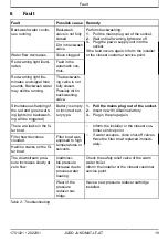
Page 17: ...WARNING A defective backflow preventer must be replaced immediately The backflow preventer may only be replaced by trained technical personnel The testing screw at the inlet connection of the built in...

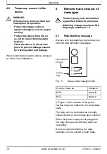
Page 18: ...by qualified technical personnel Switching voltage maximum 24 V Amperage maximum 1 A 5 1 Potential free message Devices with potential free signal relay can transmit fault indication messages a b c z...

Page 19: ...n warn ing lights no backwash ing will be triggered Battery is empty or incorrect bat tery type 1 Pull the mains plug out of the socket 2 Insert new 9V Alkaline battery 3 Plug in the plug again There...

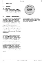
Page 20: ...k flow high water drawing level If necessary the outlet pressure setting must be readjusted To ensure the process operates success fully as long as possible regular inspec tion and routine servicing o...

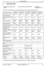
Page 21: ...ow acc to DIN EN 1567 2 3 m h 3 6 m h 5 8 m h 9 1 m h 14 0 m h Settable downstream pressure 1 5 bar 6 bar 1 5 bar 6 bar 1 5 bar 6 bar 1 5 bar 6 bar 1 5 bar 6 bar Factory setting of downstream pres sur...

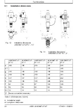
Page 22: ...1 JUKOMAT LF AT 1 JUKOMAT LF AT 1 JUKOMAT LF AT 2 A 180 195 230 301 335 A1 175 195 B 130 130 130 108 108 C 158 158 158 181 181 D 317 317 317 402 402 E 190 190 195 226 234 F 82 82 87 118 126 G 50 50 5...

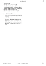
Page 23: ...e water connector mid to pipe mid G Waste water connection size G1 Waste water connection size alt 8 2 Accessories Cable for external fault signal order no 2170437 Expansion QUICKSET JQR order no 8250...

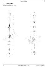
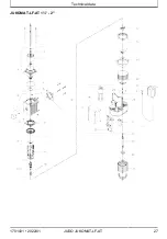
Page 24: ...Technical data 8 3 Spare parts JUKOMAT LF AT 1 24 JUDO JUKOMAT LF AT 1701431 2022 01...

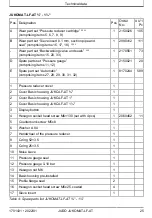
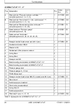
Page 25: ...9 30 31 32 1 8170244 589 1 Pressure reducer cover 1 2 Cover Basic housing JUKO LF AT 1 2 Cover Basic housing JUKO LF AT 1 1 2 Cover Basic housing JUKO LF AT 1 1 3 Display button 1 4 Hexagon socket hea...

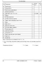
Page 26: ...head self tapping screw 3 9x13 2 27 Motor 1 28 Motor cover 1 29 Electronic control unit 1 30 9 V block battery alkaline 1 31 Power supply unit 1 32 Automatic housing 1 33 O ring 6 07 1 3 1 34 Hose co...

Page 27: ...Technical data JUKOMAT LF AT 1 2 1701431 2022 01 JUDO JUKOMAT LF AT 27...

Page 28: ...gon socket head screw set with 4 pcs 1 2170654 29 2 Countersunk screw M5x8 1 3 Washer A 8 4 1 4 Handwheel of the pressure reducer 1 5 O ring 84x4 2 6 O ring 38x4 1 7 Hexagon nut M8 4 8 Basic housing p...

Page 29: ...31 Handwheel 1 Table 5 Spare parts list JUKOMAT LF AT 1 2 1 AU Accounting unit articles without an accounting unit are only available as part of a set Replacement interval 3 years 4 years 9 Disposal P...

Page 30: ...interference immunity EN 61000 6 2 EN 61000 6 3 Harmonized Standards Safety of power transformers power sup plies reactors and similar products EN 61558 1 The observance of the mentioned directives an...

Page 31: ...aintenance log 11 Maintenance log Product designation Automatic domestic water station Order number Serial number Date Work activities performed Company Signa ture 1701431 2022 01 JUDO JUKOMAT LF AT 3...

Page 32: ...online ch judo online ch BENELUX JUDO Wasseraufbereitung GmbH Filiaal Filiale Benelux Laarbeeklaan Av du Laerbeek 72 A1 B 1090 Brussel Bruxelles Phone 32 0 24 60 12 88 Fax 32 0 24 61 18 85 E mail inf...

Reviews: