background image


REMOTE CONTROL AND MONITORING 

Using the On Board Web Server 


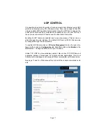
TURNING POWER ON AND OFF  - On the Control page, each of three PODs 
has associated with it a virtual On/Off button (Activate) and an On/Off indicator 
(Status). Clicking an On/Off button turns the corresponding POD on or off. 
When a POD is on the Status indicator will be green as if on. When a POD is 
off, it’s Status indicator will darken, as if off.  
 
POWER MONITORING - The Current indicator will show the amount of electric 
current flowing through a particular POD. This meter is accurate to the nearest 
0.1 amperes for levels between 0.2 and 20.0 amperes. Current measurement is 
RMS, averaged over a period of three seconds. Because the iP15 only meas-
ures current in one direction, from the outlet to the load, applications that feed 
current back to the supply (for example inductive loads such as motors) will not 
be measured accurately.  (This feature not available with the IP50/IP50-RX) 
 
SEQUENCING SETTINGS - Rather than turning each POD on and off individu-
ally, in applications where it is desired to turn the outlets on and off in a coordi-
nated sequence, a macro program can be set to turn the PODS on (1-2-3) and 
off (3-2-1) in order with the click of a virtual button. Under the Sequence head-
ing on the Control page enter a desired number of seconds for the delay of turn-
ing the PODS on and off. The default value is two seconds. Clicking the Acti-
vate button will turn the outlets on or off in the prescribed order. The status of 
the PODs is indicated below the Status heading on the Control page. 
 
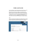
REMOTE OPERATION OF iP device - To access the iP device from a different 
network other than the one the iP device is using, you need to first assign the 
iPdevice with a PORT address on the Network setup page and then assign this 
on your router.  Log in to your router and enable the PORT FORWARDING 
feature (Sometimes called Virtual Server) using the assigned iP device’s IP 
number you chose and the port number you assigned. Each router’s port for-
warding is different. So see your routers manual for help with configuring this. 
Once you have port forwarding setup you can access the iP device from a re-
mote network by typing the IP address and PORT address into your browser 
bar. The PORT address is added to the end of the IP address separated by a 
colon.  
 
Example 200.100.075.050:80 - In this example “80” is the port address. 
 
If you have enabled the port forwarding correctly on your router you will be able 
to access the iP device from any location in the world.  


Page 12 

Summary of Contents for iP1515

Page 1: ...Quickstart Section is on Page 2 OWNER S MANUAL iP Series WEB CONTROLLED AC POWER DISTRIBUTION 12 20...

Page 2: ...user to dangerous electric shock CAUTION 2 These devices should be installed only by qualified electrical technicians using appropriate mounting hardware and correct installation tech niques Before in...

Page 3: ...figure itself at which point the Network light on the front of the unit will illuminate indicating network connectivity If the Network light blinks or does not light at all check the cable connections...

Page 4: ...be hardwired VOLTAGE INPUT for all models 120 VAC at 60 Hz POWER OUTPUTS IP1515 and RX Six NEMA 5 15R controlled one NEMA 5 15R unswitched IP1520 and RX Six NEMA 5 20R controlled one NEMA 5 20R unswi...

Page 5: ...ing it means no network connection is detected when solidly lit it means it has detected and connected to a network POD LEDs As each of the POD duplex receptacles on the back of the iP se ries turns o...

Page 6: ...rator 5 You will be presented with the login box Enter the following initial username and password these can be changed later User admin Password juicegoose Connecting to the iP device using a Crossov...

Page 7: ...168 1 77 10 The iP device login box will appear enter your login details and operate the iP device You can also configure the required IP address and any network RS232 set tings you require using the...

Page 8: ...ettings of the unit and the MAC ad dress This page is useful for retrieving all the information you may need to set up the iP device on your network If you have DHCP enabled the IP address your router...

Page 9: ...on DNS named devices allow for easier identification on a network If you wish to set the IP address manually to conform with your personal net work the fields are provided to do this You must first di...

Page 10: ...ll reboot You may hit the Cancel but ton if you decide you don t want the changes and the username passwords will remain unchanged Only the Admin login has access to the setup and configuration page T...

Page 11: ...set at a default of 19200bps RS232 communication uses COM1 Your com puter will need to be set to the same values as follows Baud rate 19200 Par ity None Data Bits 8 Stop Bits 1 Once you have configur...

Page 12: ...ress is We suggest plugging the modem into the Unswitched always on outlet of the iP device and the router in POD1 If you have a static IP address this is not an issue and the modem can also be plugge...

Page 13: ...3 and off 3 2 1 in order with the click of a virtual button Under the Sequence head ing on the Control page enter a desired number of seconds for the delay of turn ing the PODS on and off The default...

Page 14: ...uch as Windows Hyper Terminal or Micro Terminal which you can download from our website at http juicegoose com product ip 1520 html the following commands can be issued to the iP device NOTE A DEACTIV...

Page 15: ...SK XXX XXX XXX XXX Sets the subnet mask of the unit where X represents your chosen numerals SETGATEIP XXX XXX XXX XXX Sets the gateway of the unit where X represents your chosen numerals SETPDNS Sets...

Page 16: ...available to the user over TCP IP as if the user was connected to IP device over the local serial connection By default TCP feature is disabled due to security reasons This can be en abled through th...

Page 17: ...50 RX feature a patented Hybrid Filter Tech nology to clean up and prevent both normal mode line to neutral and common mode ground line surges and interference Many popular power conditioners includin...

Page 18: ...is can be en abled through the web interface The default UDP port is 30333 this can also be changed through the web interface To enable UDP feature click on iP Series Management link on the web inter...

Page 19: ...ce back up in accordance with the sequence delay currently active To enable the power loss feature click on iP Series Management link on the web interface and then click on Configuration tab You will...

Page 20: ...s similar to that which would cause a unit to fail to turn on b Follow steps outlined in the power up solution above I CANNOT CONNECT TO THE iP DEVICE VIA MY NETWORK Ensure your router has DHCP enable...

Page 21: ...ERNAME PASSWORD The only way to fix this issue is to do a factory reset of the unit as detailed be low FACTORY RESET ALL VALUES The iP device can be returned to it s default firmware values by pressin...

Page 22: ...If the problem can not be remedied if the encountered problem is not listed here and particularly if any evidence of severe or hazardous performance is observed immediately disconnect power to the iP...

Reviews: