


3
2
1
0
3
2
1
0
3
2
1
0
3
2
1
0
H
H
H
H
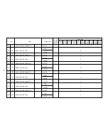
Bank No. 1
H
L
H
H
Bank No. 5
L
H
H
H
Bank No. 9
L
L
H
H
Bank No. 13
H
H
H
L
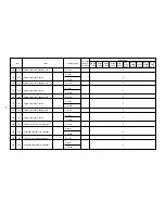
Bank No. 2
H
L
H
L
Bank No. 6
L
H
H
L
Bank No. 10
L
L
H
L
Bank No. 14
H
H
L
H
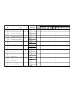
Bank No. 3
H
L
L
H
Bank No. 7
L
H
L
H
Bank No. 11
L
L
L
H
Bank No. 15
H
H
L
L
Bank No. 4
H
L
L
L
Bank No. 8
L
H
L
L
Bank No. 12
L
L
L
L
Bank No. 16
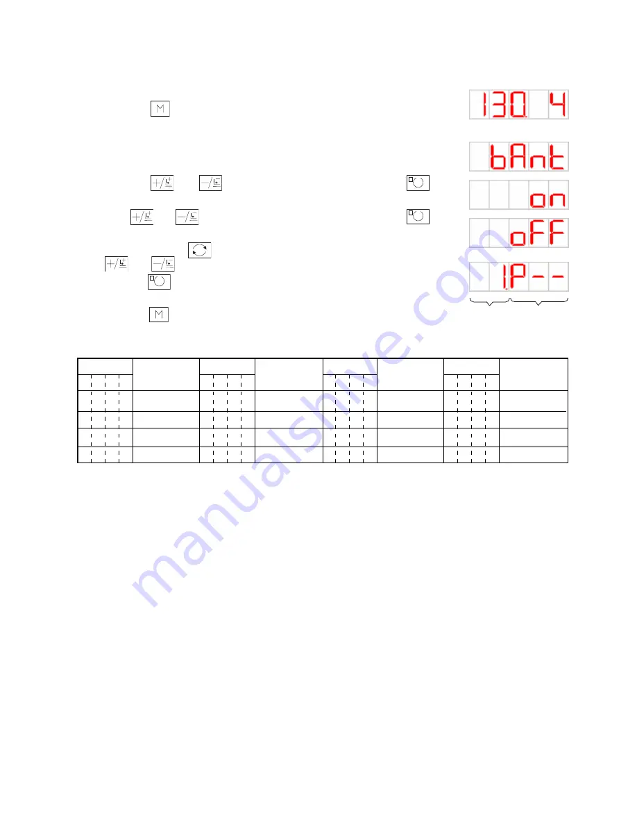
2. CP-20
The bank input terminals 0 to 3 (input Nos. 3 to 6) are assigned to arbitrary input terminals of the memory
switches Nos. 300 ~ 331.
1) When the key is continuously pressed for 6 seconds in the state that the
sewing LED is unlit, the service setup mode is assumed for the memory switches
and the bank mode is set up.
→
In regard to the method of memory switch setup, refer to the section of memory
switch data change of the Instraction Manual.
2) Using the and keys, select the bank mode and press the key.
The sewing Led is then lit up.
3) Make and key setting for bank mode ON or OFF. Press the key.
4) Register the direct pattern number for the input terminal. Input terminal changeover
is possible with the key. The direct pattern number can be selected with the
and keys.
5) Press the key to register the contents of setup. The sewing LED is unlit and
the status of memory number selection is recovered.
6) Press the key to close the memory switch setup mode. The normal status is
then recovered.
– 100 –
The upper 2
digits denote
the input ter-
minal num-
ber.
The lower 3 dig-
its denote the
pattern number.
Bank number
Bank number
Bank number
Bank number
Relationship between bank input terminals and bank numbers
Input terminal
Input terminal
Input terminal
Input terminal
H: High, L: Low (when bank input active = Low)