P 5
P 1
P 2
P 3
P 4
P 5
Pattern
X enlarge Y enlarge
Speed
Counter
Bobbin
Threading Thread tension
Ready
Thread clamp
LED
LED
LED
LED
LED
LED
LED
LED
LED
LED
1
Key
Key
Key
Key
Key
Key
2
Key
Key
Key
Key
Key
Key
3
DIPSW2
DIPSW2
DIPSW2
DIPSW2 Start SW
Presser
Presser
Presser
Presser
-1
-2
-3
-4
1SW
2SW
3SW
4SW
4
AUDET
ADDET
DDET
UDET
TG
PDET
SDET
Head fall Air pressure X motor origin
Sensor
Sensor
Sensor
Sensor
Sensor
Sensor
Sensor
SW
SW
Sensor
5
Y motor Presser motor Thread clamp Intermediate
Presser
Thread
External External
External
External
origin
origin
motor
presser motor
motor
clamp motor
input 1
input 2
input 3
input 4
sensor
sensor
origin sensor origin sensor
sensor
sensor
6
External
External
External
External
External
External
External External
External
External
input 5
input 6
input 7
input 8
input 9
input 10
input 11
input 12
input 13
input 14
7
External
External
input 15
input 16
8
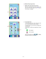
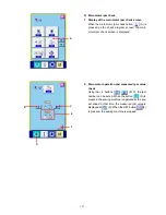
(3) Method of confirmation according to each test program No. (CP-20)
– 142 –
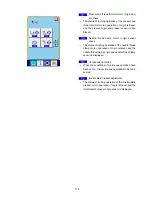
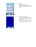
1) CP-1 (Input signal check)
It is possible to check the input status of the operation panel keys, pedal switches, and various sensors.
Display of input No.
The input number is updated by +1 each time the
and keys are pressed simultaneously.
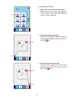
Display of the input status with the item selection LED
ON/OFF
Refer to the table below in regard to the contents of dis-
play.
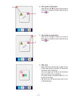
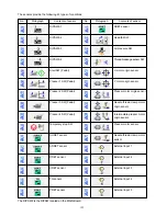
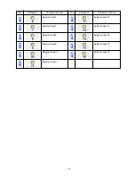
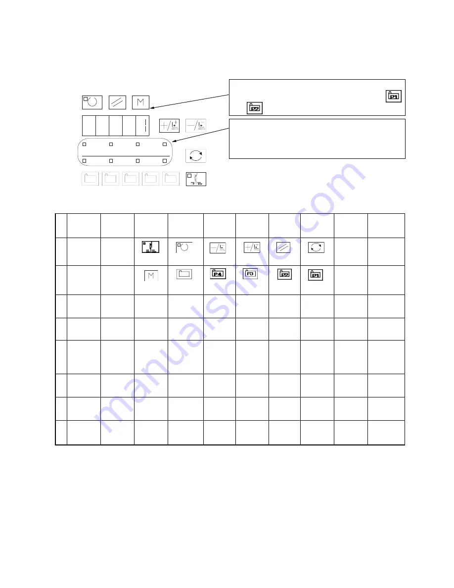
Contents of Display for each Input No.
DIPSW2 is a dip switch located on the MAIN board.
Temporary
stop
SW