
– 167 –
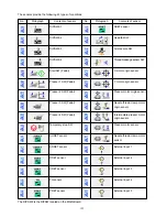
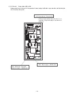
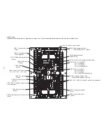
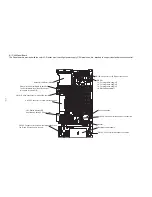
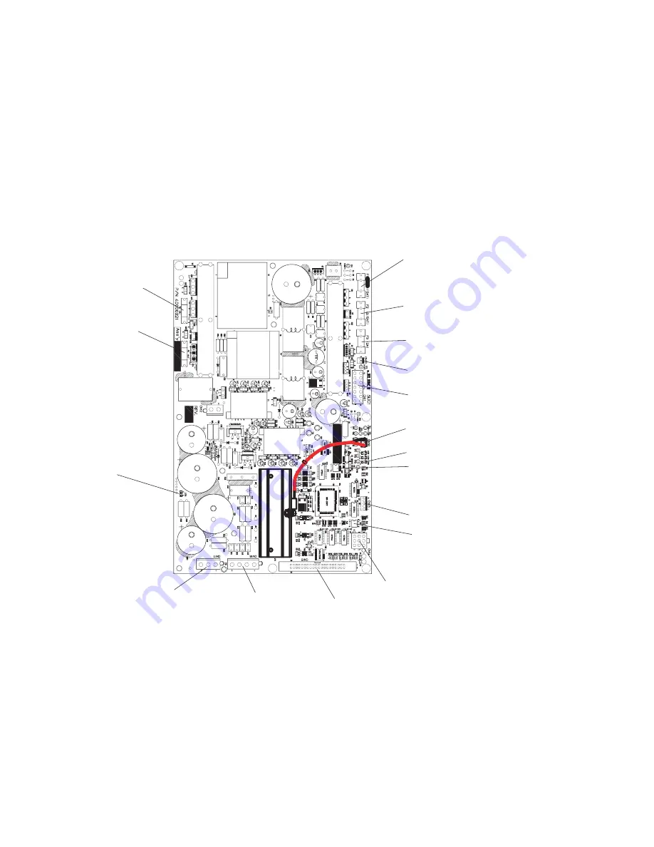
3) SDC board
The power supply is generated and error check is carried out. Main shaft control is effected, receiving the commands from the MAIN board.
LED4: For power
supply check
LED3: For operation and error check
CN18: For IPM temperature sensor
CN10: 24V for the FAN
F1: 15A
Time lag fuse
For +48V
F2: 3.15A
Time lag fuse
For +33V
F3: 2A
Fast-blow type fuse
For +24V
F4: 4A
Fuse fixed to the
board
For +48V source
primary
F5: 4A
Fuse fixed to the
board
For +33V source
primary
CN11: Power connector
→
MAIN board
+5V, +12V, +24V, +33V, +48V
DIPSW
2-1: For writing-off
2-2: For mode setting-off
2-3: For mode setting-off
2-4: For mode setting-off
DIPSW
1-1: For testing-off
1-2: For testing-off
1-3: For testing-off
1-4: Penetration force-off
CN17: For power supply
←
FLT board
CN16: For Main shaft motor
power
→
Main shaft motor
CN15: For MAIN communication
→
MAIN board
CN14: For Main shaft encoder
→
Main shaft motor
CN13: For momentary interruption
detection
←
FLT board