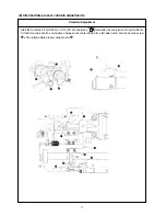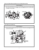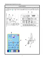
* Turn ON the power once, and turn OFF the power again after
making the intermediate presser in the lowered state.
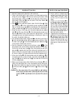
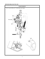
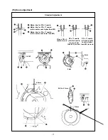
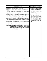
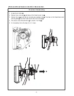
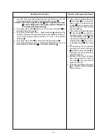
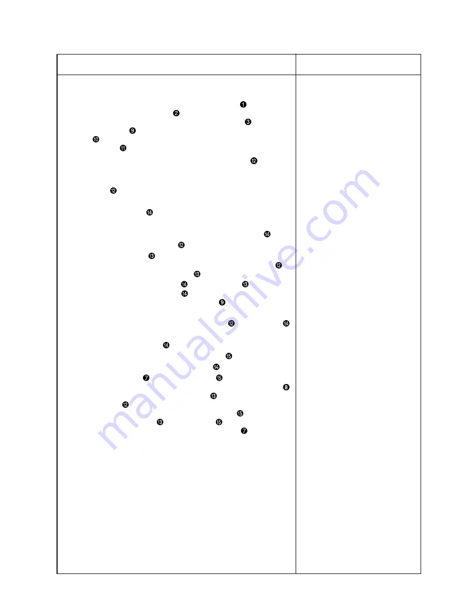
1. Turn hand wheel by hand to ascend the needle bar
.
Adjust so that lower marker line
on the ascending needle bar aligns
with the bottom end of the needle bar bushing lower
.
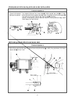
2. Loosen setscrew
in the driver. Drawing bobbin case opening lover
hook
toward you, open it to the right and left until bobbin case
opening lover
comes off.
(Caution) At this time be careful not to let inner hook
come off
and fall.
3. Refer to 5. below and make tentative adjustments of timing for the
inner hook
.
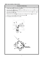
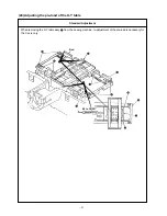
4. Turn the pulley by hand and make adjustments for the needle loca-
tion block of the driver
by bending it in the direction of Arrow A so
that the clearance b attains 0mm to 0.5mm between the needle tip
and the lowest end of the needle location block of the driver
when
the needle tip of the inner hook
is protruded by 0.5mm from the
right end of the needle
.
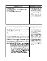
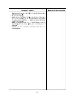
5. Make an adjustment so that the blade point of the inner hook
is
aligned with the center of the needle
, and that the clearance be-
tween the front end of the driver
and the needle
is 0 mm be-
cause the front end of the driver
receives the needle to prevent
needle bending. Then, tighten the set screw
securing the driver.
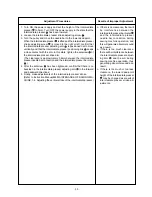
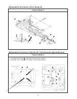
6. Make adjustments so that the clearance (C) in the revolving direction
attains 0.3mm to 0.6mm between the inner hook
and the driver
by bending the inner hook holder block (reverse side of the needle
location block) of the driver
in the direction of the arrow (D).
(Caution) Make sure not to damage the shuttle
race plane while
making adjustment of the driver
.
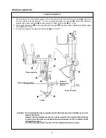
7. Loosen the set screw
securing the shuttle
, and adjust the front-
rear position of the shuttle by rotating the shuttle adjusting shaft
so that the clearance between the needle
and the blade point of
the inner hook
becomes 0.05 to 0.1 mm.
8. After adjusting the front-rear position of the shuttle
, set the clear-
ance between the needle
and the shuttle
to 7.5 mm by adjust-
ing the rotating direction, and tighten the set screw
securing the
shuttle.
– 28 –
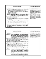
Adjustment Procedures
Results of Improper Adjustment


