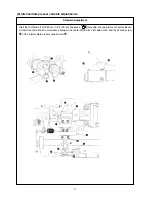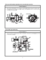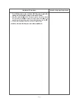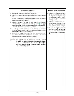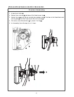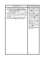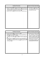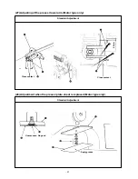
1. Apply a proper amount of grease (Juki Grease A) to the grooved cam block of the cam
, the peripheral cam
block, and the rollers of the presser bar lifter link
and the thread trimmer link
. Refer to “10.-(4) Parts to
which grease • lock-tight is applied o TENSION RELEASE & THREAD TRIMMER MECHANISM
COMPONENTS.”
2. While the cam
is being inserted in the shaft of the presser lifting motor
, mount the assembly on the
sewing machine frame and tighten the four set screws
. The insertion of the cam should be done gently in
order not to hurt the bearing
.
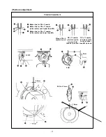
3. Clearance B toward the presser bar lifter link
and Clearance A toward the thread trimmer link
should be
equally distributed. For this purpose, adjust the position of the cam
and fix it with the use of the two set
screws
. (Apply the screws to the flat section at both ends of the shaft.)
* If it is difficult to examine Clearance B, Clearance A should be adjusted to 0.5mm ~ 0.7mm during assembly.
4. Mount the sensor slit
with the two set screws
so that the end plane of the motor shaft can approxi-
mately coincide with that of the sensor slit
. (Join the flat section for installation.)
* Confirm that the slit plate of the sensor slit
does not interfere with the presser bar lifter sensor.
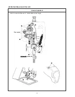
5. Refer to “3.-(17) Thread trimmer and presser origin sensor adjustment” and make sensor adjustments.
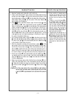
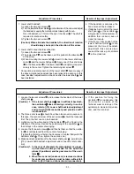
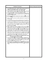
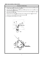
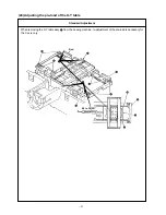
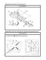
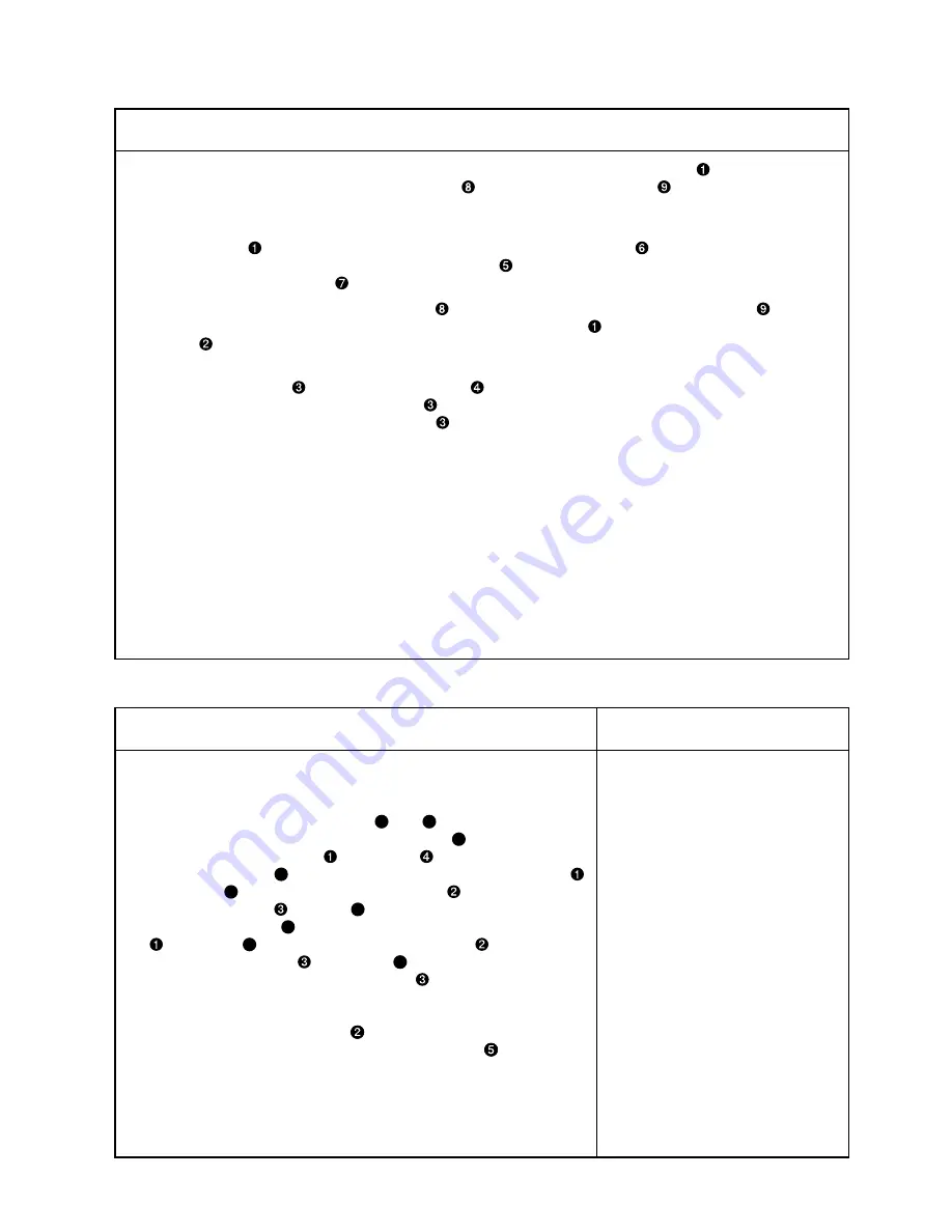
1. Start the test mode I07 (IP-400) or CP-6 (CP-20).
2. Tread on the pedal for the retrieval of the thread trimmer and presser
bar lifter (cam) origin.
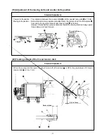
3. Make sure that the standard holes (
A
and
B
) of the thread trimming
motor stand are aligned with the standard hole
C
of the thread trim-
mer and presser lifter cam
using a bar
.
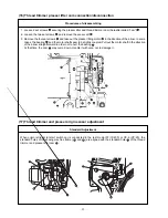
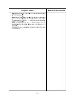
4. If the standard hole
C
of the thread trimmer and presser lifter cam
is too high (
E
direction), loosen the set screw
and move the sen-
sor mounting plate
upward (
E
direction) and secure it.
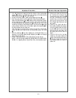
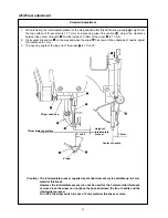
If the standard hole
C
of the thread trimmer and presser lifter cam
is too low (
D
direction), loosen the set screw
and move the
sensor mounting plate
downward (
D
direction) and secure it.
After securing the sensor mounting plate
, conduct origin retrieval
by pressing the pedal to make sure that the standard holes are aligned.
5. Repeat the above steps 2 to 4 until the coincidence is confirmed.
(Caution) Tighten the set screw
after confirming that there is no
interference between the sensor slit plate
and the sen-
sor.
o If the standard holes are not
aligned, the thread trimming
timing error occurs and defective
thread trimming and unthreading
at the beginning of sewing may
be caused.
– 30 –
Adjustment Procedures
Results of Improper Adjustment
Procedures of assembling


