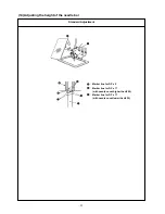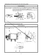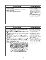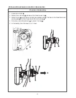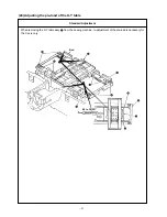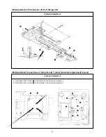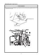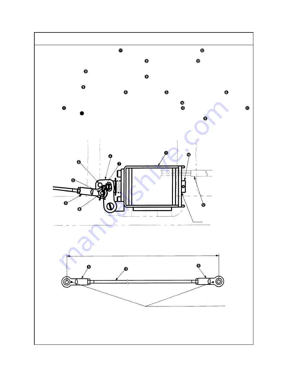
1. For incorporating the AT solenoid unit
into the system, run the solenoid cable
from the rear of the AT
solenoid unit to the rear end of the machine arm.
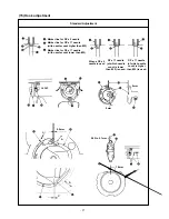
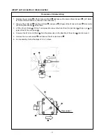
2. The center-to-center distance between the AT joints
of the AT connector rod
is 299 mm for S type and
301 mm for H type.
When the AT joints
are disassembled or assembled, make sure that the center-to-center distance is
correct, and that the front and rear of the AT joints
are parallel. Failure to observe this may cause AT
malfunction resulting in incorrect thread tension.
(When the AT joint
is turned 4 times, the feed move amount comes to attain 2mm.)
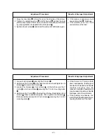
3. For the pin block of the AT link unit (rear)
, use the pin block
for H type and the pin block
for S type.
The wrong pin position may cause AT malfunction resulting in incorrect thread tension.
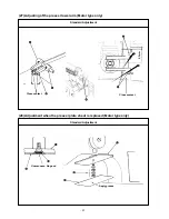
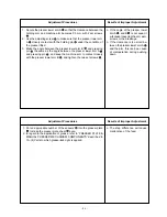
4. After completion of all assembly work, make sure that the thrust collar
closely contacts with the AT sole-
noid unit
. If there is a clearance between them, loosen 2 set screws
and move the AT solenoid unit
to the rear (Arrow
F
) and secure it again.
* If the above-mentioned center-to-center distance is great between the AT joints
, the clearance will be
opened wider.
– 38 –
Close contact
S type: 299mm, H type: 301mm
Secure parallelism between plane and plane.
Procedures of assembling


