
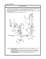
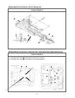
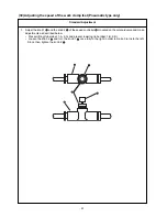

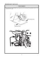
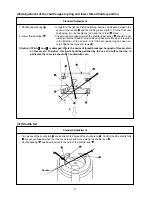


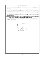

1. Make an origin setting gauge
as shown in the figure, and attach it
to the work clamp foot
.
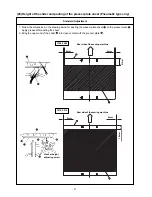
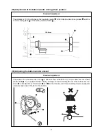
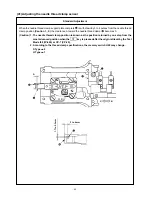
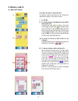
1. Start the test mode I06 (IP-400), or CP-2 (CP-20).
2. When the star pedal is depressed, the feed moves to the mechanical
origin and stops.
3. Lower the needle and check the right and left displacement based on
the engraved marking of the origin.
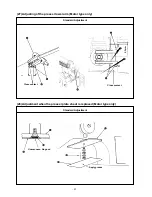
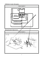
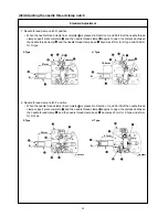
4. When the engraved marking of the origin is found to be displaced in
Direction A from the needle tip, loosen the two set screws
and
adjust the sensor mounting plate
in Direction C. After adjustments,
tighten the two set screws
.
5. When the engraved marking of the origin is found to be displaced in
Direction B from the needle tip, loosen the two set screws
and
adjust the sensor mounting plate
in Direction D. After adjustments,
tighten the two set screws
.
(Caution) After the adjustment, make sure that the slit plate does
not interfere with the sensor
.
– 52 –
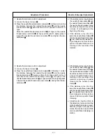
Adjustment Procedures
Results of Improper Adjustment
Adjustment Procedures
Results of Improper Adjustment


