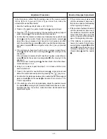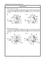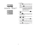
In the first place, confirm that the setting value of the memory switch
U69 is [0] for S Type and [1] for H Type. Since then, make the
adjustments as specified below.
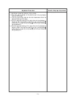
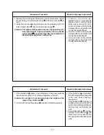
1. Start the Test Mode I08 (IP-400) or CP-7 (CP-20).
2. Tread on the pedal for needle thread clamp
origin retrieval.
3. Press the key twice and set the needle thread clamp support
plate complete
in the needle thread clamp position.
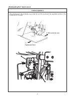
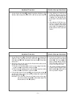
4. Confirm that the clearance A becomes 0 between the needle thread
clamp
and the needle thread clamp support plate complete
when the [–] key is pressed 3 to 4 times (for 3 to 4 pulses), and that
both the needle thread clamp
and the needle thread clamp sup-
port plate complete
move together when the [–] key is pressed
again.
5. If the clearance A becomes 0 with 5 or more pulses, loosen the set
screw
and fix the sensor mounting plate
after moving it in the
direction B.
If the clearance A becomes 0 with less than 3 pulses, loosen the set
screw
and fix the sensor mounting plate
after moving it in the
direction C.
After the sensor mounting plate
has been fixed, check the above-
mentioned steps 2. to 4.
6. Using 3 to 4 pulses, repeat the steps 2. to 5. above until the clear-
ance A becomes 0.
7. Tread on the pedal for needle thread clamp
origin retrieval and
define the most advanced position by pressing the key once.
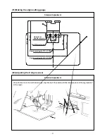
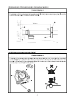
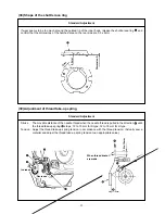
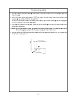
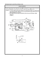
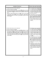
8. Confirm that the distances between the needle thread clamp support
plate complete
and the needle
are kept at 3 to 4mm and 1.7 to
2.3mm, respectively.
9. If the distance is found to be inadequate, adjust the position toward
the needle
according to (40) Needle thread clamp device connec-
tion/disconnection. Since then, make the above-mentioned sensor
adjustments again.
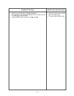
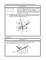
o If there are too many pulses used
until the clearance A becomes 0,
this can be a cause of unthreading
at the beginning of sewing.
o If the number of pulses is too small
until the clearance A becomes 0,
the resistance toward the needle
thread becomes large and this
can be a cause of thread break-
age at the beginning of sewing.
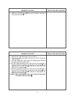
o If the distance is improper be-
tween the needle thread clamp
support plate complete
and the
needle
, this will give rise to in-
terference between the needle
thread clamp
and the needle
.
– 64 –
Adjustment Procedures
Results of Improper Adjustment

