– 72 –
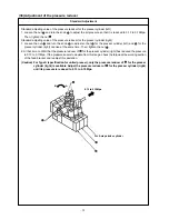
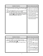
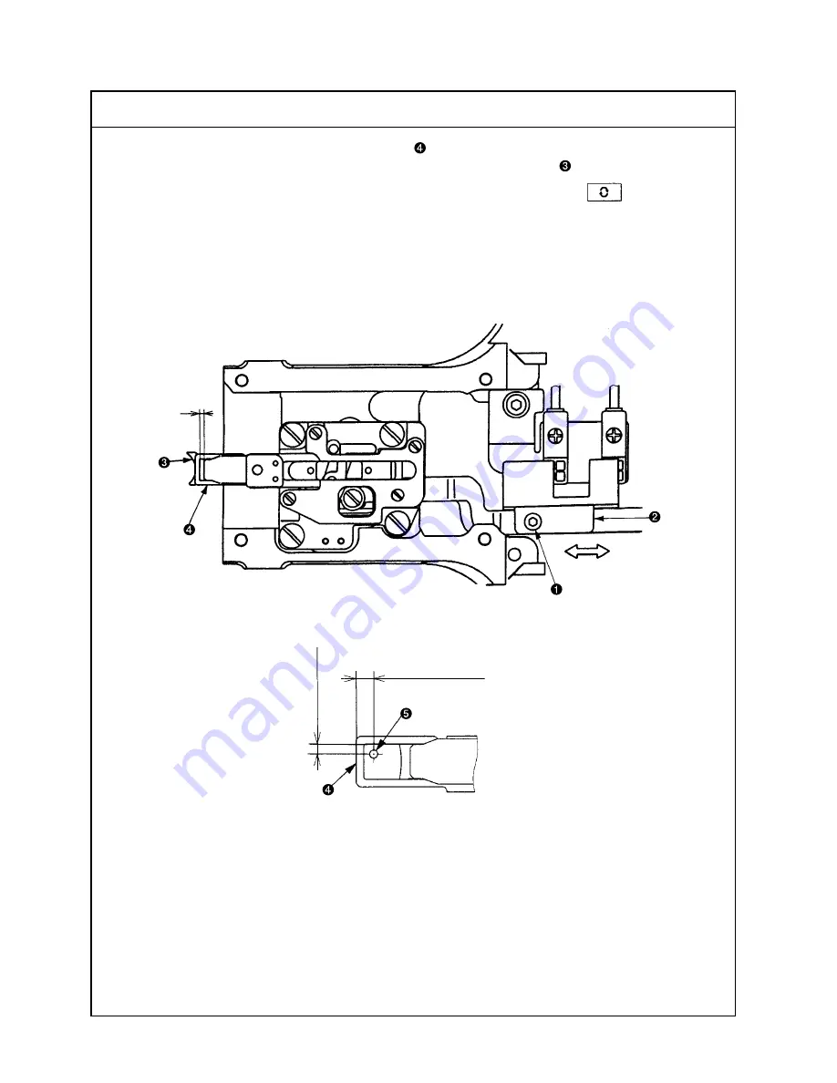
When the needle thread clamp support plate complete
is withdrawn by 3 to 4 pulses from the needle thread
clamp position (Caution 1., 2.) the clearance A toward the needle thread clamp
becomes 0.
(Caution) 1. The needle thread clamping position is defined by pressing the key after origin
retrieval in the test mode I08 (IP-410). This position is defined where it is returned by one
step from the most advanced position.
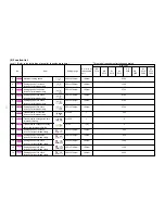
2. According to the thread clamp specifications, the memory switch U69 may change.
S Type
→
→
→
→
→
0
H Type
→
→
→
→
→
1
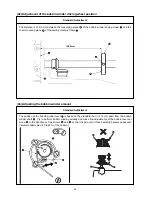
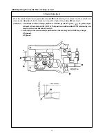
(49) Adjusting the needle thread clamp sensor
Standard Adjustment
C
B
A
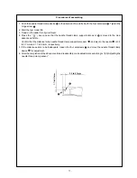
3.3 to 3.7mm
1.7 to 2.3mm

