background image

– 5 –

3

3

2

Within 0.3 mm

3


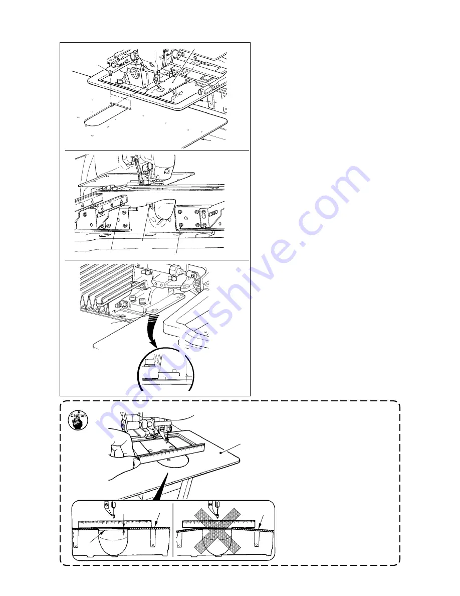
1.  Fix the throat plate auxiliary 

cover  

so that is higher 

than the throat plate 

(within 

0.3 mm). When it is lower than 

the throat plate 

2

, needle 

breakage or the like due to the 

defective feed will be caused.


2.  Confirm by putting a ruler or 

the like that the throat plate 

auxiliary cover 

is horizon-

tally installed. If not, throat 

plate auxiliary cover 

3

 and 

lower plate 

1

 come in contact 

partially with each other, and 

abnormal worn-out will be 

caused.

3

7

6

2

1

9

45

8

0.8 

to

1.0mm

to 

1.0mm1.0mm

1)  Move the cloth feed base to the rear, and 

place throat plate auxlary cover (asm.) 

3

 from between lower plate 

1

 and 

throat plate 

2

. At ths tme, be careful not 

to bend or damage lower plate 

1

.

2)  Temporarily fix throat plate auxiliary 

cover (asm.) 

3

 wth throat plate auxl-

ary cover setscrew 

5

 and washer 

4

.

3)  Temporarily fix throat plate auxiliary 

cover (asm.) 

3

 to the machne bed 

wth throat plate auxlary cover support 

setscrews 

6

 (10 pcs.).

4)  Fx throat plate auxlary cover (asm.) 

3

 to the machne bed wth two coun-

ter-sunk screws 

7

.

5) Move the cloth feed base to the left 

front, move up and down throat plate 

auxlary cover (asm.) 

3

 so that a ds-

tance of 0.8 to 1.0 mm s provded be-

tween the bottom surface of lower plate 

nstallng base 

8

 and the top surface 

of throat plate auxlary cover (asm.) 

3

and fix setscrews 

6

.

6)  Perform the smlar work by movng the 

cloth feed base to the rght front.

7)  Fx throat plate auxlary cover setscrew 

5

.

8)  Referrng to the cauton below, perform 

postonng of the throat plate auxlary 

cover. When the postonng s not per-

formed enough, perform the postonng 

after loosenng once throat plate auxl-

ary cover setscrew 

5

 and throat plate 

auxlary cover base setscrews 

9

.

[When using area 3020]

Summary of Contents for AMS-221EN/IP-420

Page 1: ... ENGLISH AMS 221EN IP 420 Instruction Manual CompactFlash TM is the registered trademark of SanDisk Corporation U S A ...

Page 2: ...take up spring 13 5 OPERATION OF THE SEWING MACHINE 14 5 1 Sewing 14 5 2 Needle thread clamp device 15 5 3 Adjusting the intermediate stop position of the feeding frame left For the separately driven feeding frame with a double stepped stroke function 17 5 4 How to use the plastic blank supplied with the machine as an accessory For the separately feeding frame with a double stepped stroke function...

Page 3: ...section at the time of combination sewing 56 1 Pattern input screen 56 2 Sewing screen 58 2 22 Performing combination sewing 60 1 Selection of combination data 60 2 Creating procedure of the combination data 61 3 Deleting procedure of the combination data 62 4 Deleting procedure of the step of the combination data 62 2 23 Using the simple operation mode 63 2 24 LCD display when the simple operatio...

Page 4: ... 5 The moving knife and counter knife 105 1 6 Needle thread clamp device 106 1 7 Thread breakage detector plate 106 1 8 Replenishing the designated places with grease 107 1 Location where exclusive grease is provided 108 2 Points to be applied with JUKI Grease A 108 3 Points to be applied with JUKI Grease B 110 1 9 Draining waste oil 112 1 10 Amount of oil supplied to the hook 112 1 11 Replacing t...

Page 5: ...ing speed limitation 200 to 2 800 sti min Scale 100 sti min steps 18 Pattern selection facility Pattern No selection method Main body 1 to 999 Media 1 to 999 19 Bobbin thread counter UP DOWN method 0 to 9 999 20 Sewing counter UP DOWN method 0 to 9 999 21 Memory back up In case of a power interruption the pattern being used will automatically be stored in memory 22 2nd origin setting facility Usin...

Page 6: ...1 Machine head 2 Wiper switch 3 Temporary stop switch 4 Feeding frame 5 Intermediate presser 6 Thread stand 7 Operation panel IP 420 8 Power switch also used as the emergency stop switch 9 Control box 0 Foot pedal 1 2 3 4 6 7 8 9 0 5 ...

Page 7: ...nsport the sewing machine In case error 302 occurs when the sewing machine works after setup loosen the safety switch fitting screw with a screwdriver and lower the switch 2 to the downside of the sewing machine 3 1 Removing the bed fixing bolt 3 2 Adjusting the safety switch ...

Page 8: ...Fix the throat plate auxiliary cover to the bed with two oval counter sunk screws 8 5 Refer to the items of the caution per form positioning of the throat plate aux iliary cover and fix setscrews 5 and 7 When the positioning is not enough loosen setscrews 9 and 0 once and perform the positioning 0 3 8 6 7 2 1 9 45 1 The stay and the like are set to the throat plate auxiliary cover and the fitting ...

Page 9: ... auxil iary cover setscrew 5 and washer 4 3 Temporarily fix throat plate auxiliary cover asm 3 to the machine bed with throat plate auxiliary cover support setscrews 6 10 pcs 4 Fix throat plate auxiliary cover asm 3 to the machine bed with two coun ter sunk screws 7 5 Move the cloth feed base to the left front move up and down throat plate auxiliary cover asm 3 so that a dis tance of 0 8 to 1 0 mm...

Page 10: ...rod 2 3 4 Installing the panel 1 Open cover 1 and remove cable 2 once Then connect it again to the panel on the top surface of the table after passing it through the hole in the table 2 Fix operation panel installing plate 3 to an op tional place on the table with two wood screws 4 Install the panel at the position where X move cover or head grip does not interfere with it since breakage of the pa...

Page 11: ...able is reached If a 20 kg or more load is necessary to be applied to the position of machine head grip 1 in order to lift the machine head gas spring 5 has outgassed Be sure to replace the gas spring with a new one While raising the sewing machine gas spring 5 works to move the sewing machine in the direction of the arrow when the sewing machine is inclined by approximately 45 degrees of an angle...

Page 12: ...feeding frame 3 to the rightmost position since X feed cover 4 interferes with the machine table causing breakage 3 When the machine is raised clean portion A of the bottom face of the machine to pre vent the surface of the machine table from being stained with oil 6 Machine head in the fixed state To return the sewing machine to its initial position follow the steps of procedure described below 1...

Page 13: ...ity of the air supply When the supply air contains a considerable amount of moisture Ambient environment When our machine is installed at a place where the temperature greatly changes in the morning and in the evening from that in the daytime or freeze is like to occur In the aforementioned cases be sure to install an air dryer Most troubles in the air solenoid valves are caused by carbon Be sure ...

Page 14: ...an extended period of disuse use the machine after lubricating a small amount of oil to the hook portion For remov ing the shuttle see 1 2 Adjusting the needle to shuttle relation p 102 2 Apply one drop of oil to the hook race 1 part to spread on it The oil tank which is filled with oil is only for lubricating to the hook portion It is possible to reduce the oil amount when the number of rotation ...

Page 15: ...obbin case insert it with the latch tilted until click sounds If it is not fully inserted bobbin case 2 may slip off during sewing 1 3 2 4 2 Attaching the needle 1 2 WARNING Turn OFF the power before starting the work so as to prevent accidents caused by abrupt start of the sewing machine Loosen setscrew 1 and hold needle 2 with the long groove facing toward you Then fully insert it into the hole ...

Page 16: ...t in an inconsistent state 2 1 4 6 Adjusting the thread tension If thread tension controller No 1 1 is turned clockwise the length of remaining thread on the needle after thread trimming will be shorter If it is turned counterclockwise the length will be longer Shorten the length to an extent that the thread is not slipped off Adjust needle thread tension from the operation panel and bobbin thread...

Page 17: ...ng of intermediate presser height at the time of delivery Memory switch U 105 1 When raising the intermediate presser height turn the pulley by hand to lower the needle bar and confirm that the needle bar does not interfere with the intermediate presser When using DP X 5 needle use the sewing machine with the height of 3 5 mm or less 2 Take care not to get your hands and fingers caught in the feed...

Page 18: ...ng 4 After the sewing machine completes sewing the needle point will return to the start point and the feeding frame will go up A B 2P pedal 2 Place a workpiece to be sewn on the sewing product under the feeding frame left Lightly depress pedal B and the feeding frame left will stop in its intermediate stop position Release the pedal and the feeding frame left will rise back to the initial positio...

Page 19: ...ue has been set to 1 H type thin thread at the time of delivery Commendable value is Set value 1 for thread count 50 to 8 Set value 2 for thread count 20 to 5 and Set value 3 for thread count 5 to 2 The value will change in accordance with the kind and thickness of the actual thread and the kinds of materials to be sewn Set the value by adjusting to the state of needle thread on the wrong side of ...

Page 20: ...bobbin thread at the sewing start appears on the right side of material reduce thread tension at the sewing start 2 to 3 stitches and bobbin thread becomes less conspicuous Example of setting Tension of 1 to 2 stitches at the sewing start is 20 when sewing tension setting is 35 For setting of tension at the start of sewing see of 2 8 1 Changing the thread tension value p 35 1 Thread at the start o...

Page 21: ...he feeding frame left is capable of stopping in the intermediate stop position 5 4 2 1 6 3 5 4 How to use the plastic blank supplied with the machine as an accessory For the separately feeding frame with a double stepped stroke function 1 Machine the plastic blank supplied with the machine according to the stitching shape 2 Attach the plastic blank to the feeding frame as illustrated in the figure...

Page 22: ...sed 2 Using the data M3 data of AMS D series with AMS 221EN There are two ways to use M3 data with AMS 221EN 1 Reading by using IP 420 Use PC personal computer and copy file AMS AMS00xxx M3 of M3 from floppy disk of AMS D to AMS of media Insert the media to IP 420 and select Pattern No xxx from M3 data 2 Changing to vector format data using PM 1 Change to the vector format data with PM 1 For the d...

Page 23: ...ose the cover By closing the cover it is possible to access If the media and the cover come in contact with each other and the cover is not closed check the following matters Check that the media is securely pressed until it goes no further Check that the inserting direction of the media is proper 1 When the inserting direction is wrong panel or media may be damaged 2 Do not insert any item other ...

Page 24: ...fter completion of copying the data remove the USB device Remove the USB device Put the cover back in place Cautions when using the media Do not wet or touch it with wet hands Fire or electric shock will be caused Do not bend or apply strong force or shock to it Never perform disassembling or remodeling of it Do not put the metal to the contact part of it Data may be disappeared Avoid storing or u...

Page 25: ...n the IP panel until it will go no further Do not turn the power OFF while the data on the USB flash drive is being accessed 2 USB specifications Conform to USB 1 1 standard Applicable devices 1_ ____ Storage devices such as USB memory USB hub FDD and card reader Not applicable devices_ __CD drive DVD drive MO drive tape drive etc Format supported ______FD floppy disk FAT 12 Others USB memory etc ...

Page 26: ...formation screen can be performed 4 COMMUNICATION key Changeover of the data input screen and the communication screen can be performed 5 MODE key Changeover of the data input screen and the mode changeover screen which performs various detail settings can be performed 6 Contrast control 7 Brightness control 8 CompactFlash TM eject button 9 CompactFlash TM slot 0 Cover detection switch 1 Connector...

Page 27: ...utton This button scrolls the button or the display in the downward direction RESET button This button performs the release of error NUMERAL INPUT button This button displays ten keys and input of numerals can be performed CHARACTER INPUT button This button displays the character input screen Refer to 2 14 Naming users pattern p 45 RESSER LOWERING button Presser is lowered and the presser lowering...

Page 28: ...whenever the power is turned ON 2 Select the pattern No you desire to sew When the power is turned ON the data input screen is dis played Pattern No button A whichs selected at present is displayed in the center of the screen Press the button to se lect the sewing shape For selecting procedure of the sewing shape refer to 2 5 Performing sewing shape selection p 30 When READY key B is pressed the b...

Page 29: ... frame needle interferes with the feeding frame during sewing and there is a danger of needle breakage or the like 2 When the presser is going up be careful that your fingers are caught with the presser since the presser moves after coming down 3 When turning OFF the power without pressing READY key the set value of Pat tern No X enlargement reduction ratio Y enlargement reduction ratio Max sew in...

Page 30: ...n new register screen is displayed Refer to 2 13 Performing new register of users pattern p 44 Pattern button name input screen is displayed Refer to 2 14 Naming users pattern p 45 Effective ineffective of thread clamp is selected Thread clamp ineffective Thread clamp effective Intermediate presser is lowered and the intermediate presser reference value change screen is displayed Refer to 2 6 Chan...

Page 31: ... value setting button is displayed Refer to 2 6 Changing item data p 32 Scale rate in X direction of sewing shape being selected at present is displayed on this button When the scale input is set to non selection by setting memory switch the button goes out and the X scale is displayed Refer to 2 6 Changing item data p 32 Actual size value in Y direction of sewing shape being selected at present i...

Page 32: ...oduct is difficult because of interruption of needle tip p 39 Effective ineffective of the thread clamp is selected Thread clamp ineffective Thread clamp effective Intermediate presser is lowered and the intermediate presser reference value change screen is displayed Refer to 2 6 Changing item data p 32 This button returns the presser to the start of sewing and raises the presser at the time of te...

Page 33: ... sewing shape being selected at present is displayed Existing counter value is displayed on this button When the button is pressed the counter value change screen is displayed Refer to 2 12 Using counter p 41 The counter display can be changed over among the sewing counter No of pcs counter and bobbin counter Refer to 2 12 Using counter p 41 Step sewing screen is displayed Checking of the pattern ...

Page 34: ...e kind of sewing shape There are 4 kinds below of the sewing shape Select the kind you desire from among them Pictograph Name Users pattern Vector format data M3 data Sewing standard format Maximum number of patterns 999 999 999 999 Select the sewing shape you desire from SEWING SHAPE SELECTION buttons E and press ENTER F button The sewing shape list screen corresponding to the kind of sewing shap...

Page 35: ... the sewing shape is determined and the data input screen is displayed When the sewing shape is users pattern the screen as A is displayed PATTERN NO SELECTION button J that is registered to users pattern is displayed Press the button of PATTERN NO you desire to select When VIEWER button K is pressed the shape of the pattern No selected is displayed and you can confirm it H G J I K A ...

Page 36: ...nlargement and reduction can be performed with in crease decrease of pitch When X Y scale rate is individually set in case of circle or arc or X Y enlargement and reduction are repeated the sewing is changed to point sewing and the shape may not be kept Enlargement and reduction can be performed by increase decrease of pitch In this case set and read X Y scale rate in the pattern list screen Max i...

Page 37: ...ormed since the reduction ratio is excessive ly small E045 Pattern data error is displayed 3 When the scale rate is changed with increase decrease of number of stitches pitch is fixed mechanical control command inputted to the points other than the shape point is deleted H I When X Y enlargement reduction ratio thread tension intermedi ate presser adding deleting of thread tension command or addin...

Page 38: ...n When the COMMAND SEARCH BACKWARD button F is pressed the feed automatically moves to the sew ing start position To stop the feed press button C D E F G or H When INTERMEDIATE PRESSER button G is pressed the intermediate presser is raised or lowered This button is not displayed when MEMORY switch U103 is set at 0 zero 5 Finish checking the shape When PRESSER INITIAL POSITION button H is pressed t...

Page 39: ...mand display A is moved forward and backward When you keep pressing the button C or D the moving speed increases Indicated value B is the absolute value Thread tension value Thread tension command value When COMMAND SEARCH FORWARD button E or BACKWARD button F is pressed the feed moves forward or backward from the current point to reach the needle entry point where the first thread tension command...

Page 40: ...ATE PRESSER button G is pressed the intermediate presser is raised or lowered This button is not displayed when MEMORY switch U103 is set at 0 zero When PRESSER INITIAL POSITION button H is pressed the work clamp moves to its origin and the screen is restored to the sewing screen When COMMAND DELETE button I is pressed the screen for deleting the command as shown in A is displayed When J is presse...

Page 41: ...DIATE PRESSER UP DOWN button C FEED BACKWARD button D FEED FORWARD button E and RETURN TO ORIGIN button F are displayed in the screen 1 When the presser is raised and the operation is stopped on the way because of the trouble of for getting to enter the bobbin case or the like press PRESSER UP button G and turn OFF the power 2 PRESSER UP button G is not displayed when the presser is of pneumatic t...

Page 42: ...M button B to perform thread trim ming When PRESSER UP button G is pressed the presser goes up Turn OFF the power since the operation afterwards cannot be performed When thread trimming is performed INTERMEDIATE PRESSER UP DOWN button C FEED BACKWARD button D FEED FORWARD button E and RETURN TO ORIGIN button F are displayed in the screen 1 When the presser is raised and the operation is stopped on...

Page 43: ...hen setting of sewing product is difficult because of interruption of needle tip 2 Move the pattern Lower the presser and input the move direction with DIREC TION key B A B The moving amount set can be effective only in the sewing screen When the screen returns to the input screen by press ing down READY key the moving amount set is erased ...

Page 44: ...ne Press STOP button B and the sewing machine stops and returns to the normal mode Or depress the start pedal again during winding bobbin and the sewing machine stops while the bobbin thread winding mode stays as it is Depress the start pedal again and the bobbin winding starts again Use this way when winding bobbin thread around plural bobbins Bobbin winder does not work immediately after turning...

Page 45: ...the existing value is equal to the set value the count up screen is displayed DOWN counter Every time the sewing of one shape is performed the existing value is counted down When the existing value is reached to 0 the count up screen is displayed Counter disuse The sewing counter does not count a finished shape even when the machine has sewn the shape The counter screen of the sewing counter is no...

Page 46: ...input the set value When 0 is inputted in the set value the display of count up screen is not performed Bobbin counter UP counter The counter increases the existing value by one every time the machine has sewn 10 stitches When the existing value is equal to the set value the count up screen is displayed DOWN counter The counter decreases from the existing value by one every time the machine has se...

Page 47: ...nge screen When you desire to revise the counter value during sewing work due to the mistake or the like press COUNTER VALUE CHANGE button A on the sewing screen The counter value change screen is displayed 2 Count up releasing procedure When the count up condition is reached during sewing work the count up screen is displayed and the buzzer beeps Press CLEAR button A to reset the counter and the ...

Page 48: ...ng new register of users pattern 3 Input the users pattern No Input the users pattern No you desire to newly register with the ten keys B It is possible to retrieve the users pattern No which has not been registered with the or button C and D 4 Determine the users pattern No Press ENTER button E to determine the users pattern NO to be newly registered and the data input screen at the time of users...

Page 49: ...button B you desire to input and the input of character can be performed As many as 255 characters to and to and symbols can be input The cursor can be moved with CURSOR LEFT TRAVEL button C and CURSOR RIGHT TRAVEL button D When you desire to delete the inputted character adjust the cursor to the position of the character you desire to delete and press DELETE button E 4 Finish the input of charact...

Page 50: ... button No which has been already registered is prohibited It is possible to retrieve the pattern button No which has not been registered with the or button C and D 4 Select the folder to be stored It is possible for the pattern buttons to be stored in five folders As many as 10 pattern buttons can be stored for one folder The folder to store the button can be selected with FOLDER SELECTION button...

Page 51: ...g users pattern p 45 Character which is registered to the pattern button No being selected is displayed Bobbin thread can be wound Refer to 2 11 Winding bobbin thread p 40 Pattern button No being selected at present is displayed on this button and when the button is pressed the pattern button No selection screen is displayed Refer to 2 17 Performing pattern button No selection p 51 Sewing shape wh...

Page 52: ...alue which is registered to the pattern button No being selected is displayed Travel amount in X direction which is registered to the pattern button No being selected is displayed Travel amount in Y direction which is registered to the pattern button No being selected is displayed X actual size value which is registered to the pattern button No being selected is displayed X scale rate which is reg...

Page 53: ...ng sewing is displayed Character which is registered to the pattern button No being sewn is displayed Scale rate in X direction which is registered to the pattern button No being sewn is displayed Actual size value in X direction which is registered to the pattern button No being sewn is displayed Effective ineffective of thread clamp is selected Thread clamp ineffective Thread clamp effective W S...

Page 54: ... No being sewn is displayed Total number of stitches of sewing shape which is registered to the pattern button No being sewn is displayed Needle thread tension value which is set to the pattern data being selected at present is displayed on this button and when the button is pressed the item data change screen is displayed Refer to 2 6 Changing item data p 32 Travel amount in X direction which is ...

Page 55: ...ed pattern button No button C which have been registered are changed over in order The contents of sewing data which have been inputted in the pattern button No are displayed in the button Here press the pattern button No button C you desire to select 4 Determine the pattern button No When ENTER button D is pressed the pattern button No selection screen is closed and the selection is finished Howe...

Page 56: ...splayed with every folder which is specified when the pattern is newly created When FOLDER SELECTION button B is pressed the pattern button to be displayed is changed Display and press the button of the pattern button No you desire to sew When it is pressed the pattern button No is selected WARNING Make sure without fail of the contour of the sewing pattern after selection of the sewing pattern If...

Page 57: ... to the actual size value input by selection of memory switch Max input range and initial value of max speed limitation D are determined with memory switch The input range of travel amount in X direction F and travel amount in Y direction G differs accord ing to the sewing range 3 Display the input screen of the item data you desire to change Data that can be changed are 11 items below A H D I L F...

Page 58: ...he sew ing screen green press READY switch to display the data input screen blue 2 Call the pattern copy screen When PATTERN BUTTON COPY button A is pressed the pattern button copy copy source selection screen is dis played 4 Determine the change of item data For example input X scale rate Press B to display the item data input screen Input the value you desire with the ten keys or or key K When E...

Page 59: ...ection state returns to the pattern button copy copy source selection screen after ap proximately two seconds Combination data can be copied in the same way 2 20 Changing sewing mode 1 Select the sewing mode When switch is pressed in the state that the pattern has been registered SEWING MODE SELECTION button A is displayed on the screen When this button is pressed the sewing mode changes alternate...

Page 60: ...ATA NEW REGISTER button COMBINATION DATA COPY button COMBINATION DATA NAME INPUT button COMBINATION DATA NAME display PRESSER DOWN button BOBBIN WINDING Description Combination data No new register screen is displayed Refer to 2 15 Performing new register of pattern button p 46 Combination pattern No copy screen is displayed Refer to 2 19 Copying pattern button p 54 Combination data name input scr...

Page 61: ...t is displayed in blue color As many as the number of inputted patterns is displayed in H and I display and button Pattern No shape number of stitches etc which are registered in H SEWING ORDER are displayed on the button When the button is pressed the pattern selection screen is displayed As many as the number of inputted patterns is displayed in H and I display and button This button is displaye...

Page 62: ...neffective Thread clamp effective Presser can be lowered and the presser down screen is displayed To raise the presser press the presser up button displayed in the presser down screen This button returns the presser to the start of sewing and raises the presser when the present presser position is on the way of sewing Combination data No being selected is displayed Pattern button No being sewn is ...

Page 63: ... this button When the button is pressed the counter value change screen is displayed Refer to 2 12 Using counter p 41 The counter display can be changed over among the sewing counter No of pcs counter and bobbin counter Refer to 2 12 Using counter p 41 Actual X size value of the sewing shape which is registered to the pattern button No being sewn is displayed X scale rate of the sewing shape which...

Page 64: ... the upper part of the screen and other combination data No buttons which have been registered are displayed in the lower part of the screen A C E F D B 3 Select the combination data No When UP DOWN button B is pressed combination data No buttons C which have been registered are changed over in order It is also possible to display the combination data No input screen using NUMBER INPUT button D an...

Page 65: ...ata are displayed in the buttons Here press the pattern No buttons you desire to select 4 Determine the pattern No When ENTER button E is pressed the pattern No se lection screen is closed and the selection is finished A C B F E D I G 5 Repeat steps 2 through 4 as many as the number of pat tern Nos you desire to register When the first register is determined the second pattern selec tion button F ...

Page 66: ...n data No Perform steps 1 to 2 of 2 22 1 Selection of combina tion data p 60 to make the state that the combination data including the step you desire to delete has been selected 2 Display the pattern No selection screen Press UP DOWN SCROLL button A to bring the PATTERN SELECT button for the step to be deleted under the selected state B Then when STEP DELETE button C is pressed the data step dele...

Page 67: ...EEN MODE SELECT button A is displayed on the screen When this button is pressed the screen mode is changed over between the nor mal operation and the simple operation When the normal operation is selected When the simple operation is selected A With IP 420 the SIMPLE OPERATION mode is available ...

Page 68: ... 64 2 24 LCD display when the simple operation is selected 1 Data input screen individual sewing User s pattern Media pattern Direct pattern A B B A F F C B C E M F N O H D G I J K Q P A L ...

Page 69: ...ting procedure the thread tension reference value is indicated on edit data display Q The thread tension value is increased decreased in increments of 1 using PLUS button J or MINUS button K Refer to 2 6 Changing item data p 32 H MAX SPEED LIMITATION SETTING button The current max speed limitation is indicated on the button When the button is pressed the max speed limitation can be changed During ...

Page 70: ...d When no edit item is selected this display is not given A MEDIA PATTERN WRITE button Data on a media pattern is written When this button is pressed the new media pattern registration screen is displayed This button is displayed when the media pattern is selected B USER S PATTERN WRITE button Data on a user s pattern is written When this button is pressed the new user s pattern registration scree...

Page 71: ... 67 A B C P O D M N C B A M A Q J H I K L R E S F G User s pattern Media pattern Direct pattern 2 Sewing screen individual sewing ...

Page 72: ... indicated on the button When the button is pressed the reference value of the thread tension can be set During the setting procedure the thread tension reference value is indicated on edit data display S The thread tension value is increased decreased in increments of 1 using PLUS button K or MINUS button L The thread tension can be changed even during sewing I INTERMEDIATE PRESSER HEIGHT REFEREN...

Page 73: ...ntly selected edit item is displayed When no edit item is selected this display is not given A SEWING DATA TYPE display The type of data read from a medium is displayed Vector form data M3 data Standard format of sewing This display is given when the media pattern is selected A PATTERN LIST button Pattern No and type which are currently selected are indicated on the button When the button is press...

Page 74: ...ATTERN No SETTING button Pattern No is set Registered pattern No is retrieved using PLUS button G and MINUS button H F PATTERN LIST button Pattern No and type which are currently selected are indicated on the button When the button is pressed the selected pattern list screen is displayed for the pattern selection G PLUS button The value for the selected item is increased in increments of the refer...

Page 75: ...ern is displayed O Y ACTUAL SIZE VALUE display The actual Y size value of the currently selected pattern is displayed P TRAVEL AMOUNT IN X DIRECTION display The amount of travel in the X direction of the currently selected pattern is displayed Q TRAVEL AMOUNT IN Y DIRECTION display The amount of travel in the Y direction of the currently selected pattern is displayed R EDIT DATA display The data w...

Page 76: ...ing and raised to its upper position at the time of a temporary stop D SEWING ORDER RETURN button The pattern to be sewn can be returned to the previous one E SEWING ORDER ADVANCE button The pattern to be sewn can be advanced to the next one F SHAPE CHECK button The shape of the pattern which is being selected is checked using PLUS button J or MINUS button K The current number of stitches is indic...

Page 77: ... needle is moved backward by one stitch L PATTERN NO TYPE display The pattern No and type of the pattern which is being selected are displayed M SEWING ORDER display The sewing order of currently selected pattern data is displayed N TOTAL NUMBER OF REGISTERS display The total number of patterns registered to the cycle pattern which is currently being selected is displayed O COMBINATION DATA NAME d...

Page 78: ... 3 MEMORY SWITCH DATA LIST p 84 2 25 Changing memory switch data 1 Display the memory switch data list screen When MODE key is pressed memory switch button A is displayed on the screen When this button is pressed the memory switch data list screen is displayed 2 Select the memory switch button you desire to change Press UP DOWN SCROOL button C and select the data item button B you desire to change...

Page 79: ...ion screen is displayed 2 Display the maintenance and inspection information screen Press maintenance and inspection information screen display button B in the information screen A B D E C Information on the following three items is displayed in the maintenance and inspection information screen Needle replacement 1 000 stitches Cleaning time hour Oil replacement time hour The interval to inform of...

Page 80: ...ive items are as follows Needle replacement A201 Cleaning time A202 Oil replacement time A203 For the grease up portion refer to the item of 1 8 Replenishing the designated places with grease p 107 3 Perform clearing remaining time up to the replacement When button C of the item you desire to clear is pressed the time of replacement clear screen is displayed When CLEAR button F is pressed the rema...

Page 81: ...n addition the function can upload the aforementioned data to the media or personal computer As the means of communication a media slot and USB port are prepared However SU 1 data server utility is necessary to perform download upload from the personal computer 1 Handling possible data Sewing data that can be handled are 4 kinds below and the respective data formats are as shown be low xxx file No...

Page 82: ...nication screen is displayed 2 Select the communication procedure There are four communication procedures as described below B Writing data from media to panel C Writing data from personal computer server to panel D Writing data from panel to media E Writing data from panel to personal computer server Select the button of communication procedure you desire 3 Select the data No When F is pressed th...

Page 83: ... A is pressed the data No plural selection screen is displayed 2 Perform the data No selection Since the list of existing data file numbers is displayed press FILE NO button B you desire to write It is possible to invert the selected state of the button with INVERSION button C 3 Determine the data No When ENTER button D is pressed the data No plural selection screen is closed and the data selectio...

Page 84: ...the during communication screen When performing writing to the pattern No which already ex ists the overwriting confirmation screen is displayed before writing When performing overwriting press ENTER button F When performing overwriting all without displaying the over writing confirmation screen press OVERWRITING button G in all cases F G ...

Page 85: ...a you desire to format to the media slot close the cover press ENTER button B and formatting starts Save necessary data in the media to the other media before formatting When formatting is performed the inside data are deleted B A When two or more media are connected to the sewing machine the medium to be formatted is determined by the predetermined priority order High Low CF TM slot USB device 1 ...

Page 86: ...s depress the start pedal without change and re start the sew ing If not press THREAD TRIM button B and perform thread trimming When performing thread trimming the feed forward back pop up is displayed 3 Adjust the presser to the re sewing position Every time FEED BACK button C is pressed the press er returns by one stitch Every time FEED FORWARD button D is pressed the presser moves forward by on...

Page 87: ... button A is pressed and the error is released the sewing screen is displayed 2 Perform sewing work again from the start When the pedal is depressed sewing starts 3 When the rest switch is not displayed When a large slip is detected the reset switch is not displayed 1 Turn OFF the power ...

Page 88: ... clamp 200 to 2800 100 sti min Thread tension of 1st stitch In case of with thread clamp 0 to 200 1 Thread tension setting at the time of thread trimming 0 to 200 1 Thread tension changeover timing at the time of thread trimming 6 to 4 1 Sewing speed of 1st stitch In case of without thread clamp 200 to 1500 100 sti min Sewing speed of 2nd stitch In case of without thread clamp 200 to 2800 100 sti ...

Page 89: ...tightened 8 to 16 1 State of the presser after end of sewing is selected Presser goes up after moving at start of sewing Presser goes up immediately after end of sewing Presser goes up by pedal operation after moving at start of sewing Presser lifting motion at the end of sewing can be set With presser up Without presser up Origin retrieval can be performed every time after end of sewing other tha...

Page 90: ...hape size change can be selected input Actual size input Thread tension output time when setting thread tension can be set 0 to 20 1 Bend position of thread clamp is selected 0 S type 1 H type thin thread 50 to 8 2 H type intermediate 3 H type thick thread 5 to 2 Thread clamp and thread clamp position selection Front position Rear position Thread breakage detection selection Thread breakage detect...

Page 91: ...o right 13 to 99 Solid presser 1 When using these items refer to Engineer s Manual Feeding frame control midway stop time open close Operation order of feeding frame by pedal operation when lifting the feeding frame by the temporary stop command in the pattern data is set 0 to 99 1 0 Solid presser 1 Right left separated presser Without priority of right left 2 Right left separated presser In the o...

Page 92: ...itch Number of stitches is fixed Jog move function mode Prohibited Parallel move 2nd origin specified later Retainer compensation motion selection of motion Without motion With motion Selection of needle upper dead point at the time of origin retrieval return to origin Without With Temporary stop thread trimming operation Automatic thread trimming Manual Thread trimming by turning Stop SW ON again...

Page 93: ...weeping above intermediate presser position where intermediate presser lowers most Sweeping below intermediate presser With without air pressure detection Without With Intermediate presser DOWN position setting Refer to 4 7 Intermediate presser height p 13 0 to 7 0mm 0 1 With without needle cooler control Without With Grease up error Clearing of number of stitches of grease up is performed Refer t...

Page 94: ...f without thread clamp 1000 Sewing speed of 4th stitch In case of without thread clamp 1500 Sewing speed of 5th stitch In case of without thread clamp 2000 Thread tension of 1st stitch In case of without thread clamp 0 Thread tension changeover timing at the time of sewing start In case of without thread clamp 5 Counter motion selection Height of eight of presser at the time of 2 step stroke 70 Bu...

Page 95: ...sewing of thread breakage detection 3 Feeding frame control pedal open close 0 5 6 Feeding frame control midway stop time open close 0 5 6 Pedal SW1 with without latch Pedal SW2 with without latch Pedal SW3 with without latch Pedal SW4 with without latch Enlarging reducing function mode Jog move function mode Retainer compensation motion selection of motion Selection of needle upper dead point at ...

Page 96: ... media is not inserted Possible to re enter after reset Previous screen E012 Read error Data read from external media cannot be performed Possible to re start after reset Previous screen E013 Write error Data write from external media cannot be performed Possible to re start after reset Previous screen E015 Format error Format cannot be performed Possible to re start after reset Previous screen E0...

Page 97: ...dle bar position missing error Needle bar is not in the predetermined position Turn hand pulley to bring needle bar to its predetermined position Data input screen E031 Air pressure drop Air pressure is dropped Possible to re start after reset Data input screen E032 File interchanging error File cannot be read Possible to re start after reset Data input screen E040 Sewing area over Possible to re ...

Page 98: ...art after reset Data input screen E221 Grease up error At the time of operation of 120 million stitches The sewing machine is put in the sewing impossible status It is possible to clear with memoryswitch Refer to 1 8 Replenishing the designated places with grease p 107 Possible to re start after reset Data input screen E302 Head tilt confirmation When head tilt sensor is OFF Possible to re start a...

Page 99: ...gram after pressing down communication switch Communi cation screen E730 Main shaft motor encoder defectiveness When encoder of the sewing machine motor is abnormal Turn OFF the power E731 Main motor hole sensor is defective or position sensor is defective Hole sensor or position sensor of the sewing machine motor is defective Turn OFF the power E733 Reverse rotation of main shaft motor When sewin...

Page 100: ...val motion Turn OFF the power E908 Y feed motor origin retrieval error When origin sensor signal is not inputted at the time of origin retrieval motion Turn OFF the power E910 Presser motor origin retrieval error When origin sensor signal is not inputted at the time of origin retrieval motion Turn OFF the power E913 Thread clamp origin retrieval error When origin sensor signal is not inputted at t...

Page 101: ...ensor of intermediate presser motor does not change at the time of origin retrieval Turn OFF the power E926 X motor position slip error 1 In case of error display during sewing Possible to re start after reset 2 In case of error display after end of sewing Possible to re start after reset 3 In case of others Turn OFF the power 1 Step screen 2 Sewing screen 3 E927 Y motor position slip error 1 In c...

Page 102: ...rn OFF the power E932 Y motor overload error Turn OFF the power E933 Thread trimming motor overload error Turn OFF the power E935 Intermediate presser motor overload error Turn OFF the power E936 X Y motor out of range error Turn OFF the power E943 MAIN CONTROL p c b trouble When data writing to MAIN CONTROL p c b cannot be performed Turn OFF the power E946 HEAD RELAY p c b trouble When data writi...

Page 103: ...ting confirmation of media Overwriting is performed OK M530 Overwriting confirmation of vector data of panel M3 data sewing standard format data simplified program data Overwriting is performed OK M531 Overwriting confirmation of vector data of media M3 data sewing standard format data simplified program data Overwriting is performed OK M532 Overwriting confirmation of vector data on personal comp...

Page 104: ... OK M544 Data corresponding to panel does not exist Data does not exist M545 Data corresponding to media does not exist Data does not exist M546 Data corresponding to personal computer does not exist Data does not exist M547 Overwriting prohibition on pattern data Overwriting cannot be performed since data exists M548 Overwriting prohibition on media data Overwriting cannot be performed since data...

Page 105: ...a breakage Customized key lock data has broken Initialization is performed OK M556 Initialization confirmation of customized data Customized key lock data is initialized OK M653 During formatting Formatting is performed M669 During data reading Data is being read M670 During data writing Data is being written M671 During data converting Data is being converted ...

Page 106: ...ion 2 3 2 3 2 3 4 6 3 4 Marker line for DP x 5 needle 5 Marker line for DP x 17 needle with needle count higher than 22 6 Marker line for DP x 17 needle with needle count lower than 22 5 1 Relation between the needle and the marker lines on the needle bar When a DP x 5 needle is used When DP x 17 needle of which needle count is lower than 22 is used When DP x 17 needle of which needle count is hig...

Page 107: ... time of standard delivery or us ing a new driver perform the adjustment of the height of driver Adjustment of height of driver 1 Adjust so that the blade point of inner hook 4 meets the center of needle 5 and tighten set screw 1 2 Bend the needle guard section of driver 6 in the direction of arrow A so that the protruding amount from the bottom end of the needle guard section of driver 6 to the t...

Page 108: ...frame still interferes with the face plate bearing and the feeding frame height does not change after the adjustment of the position of work clamp link adjust the pressure applied to the face plate bearing to lower it as far as no lateral play of the feeding frame occur At the time of delivery work clamp foot has been moved up and down to adjust the torque sliding torque of face plate bearing 7 to...

Page 109: ...d counter knife 4 To adjust move the coun ter knife Throat plate 1 2 5 4 3 WARNING Turn OFF the power before starting the work so as to prevent accidents caused by abrupt start of the sewing machine 6 18 5 mm After the origin retrieval press the SET READY key on the IP panel to verify that a clearance of 0 5 mm or more is provid ed between the top end of moving knife and the top end of needle thre...

Page 110: ...g 2 WARNING Turn OFF the power before starting the work so as to prevent accidents caused by abrupt start of the sewing machine 1 7 Thread breakage detector plate 1 Adjust so that thread breakage detector plate 1 is always in contact with thread take up spring 2 in the absence of needle thread Slack approx 0 5 mm 2 Whenever the stroke of thread take up spring 2 has been changed be sure to readjust...

Page 111: ...sed further for a certain period of time without replenishing the places with grease after the display of error No E220 error E221 Grease up error is dis played and the sewing machine fails to operate since the error can not be released even when the RESET key is pressed When error E221 Grease up error is displayed be sure to replen ish the designated places below with grease Then call the memory ...

Page 112: ...or JUKI Grease A Spare parts No JUKI Grease A 10g tube 40006323 100g tube 23640204 JUKI Grease B 10g tube 40013640 2 Points to be applied with JUKI Grease A WARNING Turn OFF the power before starting the work so as to prevent accidents caused by abrupt start or the sewing machine In addition attach the covers which have been removed before operation back in place Use grease tube A part number 4000...

Page 113: ...hrough hole 5 and tighten setscrew 4 to fill inside the busing with the grease 3 Apply JUKI Grease A also onto groove section 6 of the slide block 4 Apply JUKI Grease A onto periphery of inter mediate presser bar 7 Remove setscrew 8 from the intermediate presser bar bushing grease hole Put JUKI Grease A through inlet 9 Tighten screw 8 to fill inside the bushing with JUKI Grease A 1 Do not wipe off...

Page 114: ...d with the unit into the coupling to add the JUKI Grease B 5 Securely tighten setscrew 3 which has been removed after replenishing with the grease Adding grease onto the oscillating rock shaft pin section 3 Points to be applied with JUKI Grease B 1 Open crank rod cover 1 2 Remove setscrew 3 from the grease inlet cover located at periph ery of crank rod 2 3 Fill coupling 4 with grease through JUKI ...

Page 115: ...B onto the felt sections 3 locations peripheral shoulder screw ful crums 1 to 7 and guide groove section 8 Grease supplement to the face plate section Replenishing the presser plate with grease 1 Apply grease to the rear of presser plate 1 1 1 2 6 7 8 5 4 3 ...

Page 116: ... For solenoid and pulse motor power supply protection 3 15A time lag fuse 3 For control power supply protection 2A fast blow type fuse 1 Loosen setscrew 1 and remove setscrew 1 2 When screwing in adjustment screw 2 the amount of oil of oil pipe left 4 can be reduced 3 After the adjustment screw in setscrew 1 and fix it 1 The state of standard delivery is the po sition where 3 is lightly screwed in...

Page 117: ... cord to the power plug as shown in the figure Caution Securely perform the insulation treatment to the red terminal which is not used with insulation tape or the like When the insulation is insufficient there is a danger of electric shock or leakage current C In case of using with single phase 200V to 240V Changing the changeover connector Connect to 200V the 100 200V changeover connector of FLT ...

Page 118: ... replace it 3 The needle strikes the intermediate presser foot Correct the position of the intermediate presser foot 13 4 Fibrous dust is in the groove of the shuttle race Take out the shuttle and remove the fibrous dust from the shuttle race 5 The needle thread tension is too high Reduce the needle thread tension 12 6 The tension of the thread take up spring is too high Reduce the tension 13 7 Th...

Page 119: ...n terms of the inner diameter of the intermediate presser Increase the inner diameter of intermediate presser 3 Intermediate presser is not properly positioned in terms of the needle Adjust the eccentricity between intermediate presser and needle so that needle enters in the center of intermediate presser 8 Threads break at time of thread trimming 1 The moving knife has been improperly position Co...

Page 120: ...s S type 14 to 18 2 B242621000B ø 2 0 For medium weight to heavy weight materials H type 18 to 21 B242621000D ø 2 4 For heavy weight materials OP B242621000F ø 3 0 22 to 25 B242621000G ø 3 0 with a counterbore For extra heavy weight materials OP 18 to 25 B242621000H ø 3 0 eccentric hole For heavy weight materials to prevent skip stitching OP Needle used Intermediate presser Size Part No Size øA øB...

Page 121: ...Bar code reader Bar code function is a function to read the bar code and to switch to the corresponding sewing pattern for the applications such as the cassette identification etc By reading the bar code switching to 999 user patterns stored in the sewing machine memory and to 50 sewing data registered in the pattern button can be made To use this function AMS EN bar code option 40089238 will be r...

Reviews: