background image

– 126 – 

1-11. Changing the voltage of 100


←→


200V

WARNING : 

To prevent personal injuries caused by electric shock hazards or abrupt start of the sewing 

machine, carry out the work after turning OFF the power switch and a lapse of 5 minutes or more. 

To prevent accidents caused by unaccustomed work or electric shock, request the electric expert 

or engineer of our dealers when adjusting the electrical components.

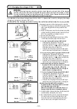
Changing procedure of the changeover connector

1.  Turn OFF the power source with the power switch 

after confirming that the sewing machine has 

stopped.

2.  Draw out the power cord from the power plug sock-

et after confirming that the power switch is turned 

OFF. Then wait for five minutes or more.

3.  Remove the front cover.

4.  Remove four screws fixing the rear cover of the 

control box and slowly open the rear cover.

A.  In case of using with 3-phase 200V to 240V

•  Changing the changeover connector

  Connect to 200V the 100

200V changeover 

connector of FLT p.c.b. 

 located on the side 

of the Box Side of the control box.

•   Connect the crimp style terminal of AC input 

cord to the power plug as shown in the figure.

B. In case of using with single phase 100V to 120V

•   Changing the changeover connector

  Connect to 100V the 100

200V changeover 

connector of FLT p.c.b. 

 located on the side 

of the Box Side of the control box.

•   Connect the crimp style terminal of AC input 

cord to the power plug as shown in the figure.

(Caution) Securely perform the insulation  

treatment to the red terminal which is not used 

with insulation tape or the like. (When the 

insulation is insufficient, there is a danger of 

electric shock or leakage current.)

C. In case of using with single phase 200V to 240V

 •  Changing the changeover connector

  Connect to 200V the 100

200V changeover 

connector of FLT p.c.b. 

 located on the side 

of the Box Side of the control box.

 •  Connect the crimp style terminal of AC input 

cord to the power plug as shown in the figure.

(Caution) Securely perform the insulation  

treatment to the red terminal which is not used 

with insulation tape or the like.

  (When the insulation is insufficient, there is a 

danger of electric shock or leakage current.)

5.  Check that the change has been performed with-

out fail before closing the rear cover.

6.  Be careful that the cord is not pinched between 

the rear cover and the control box main unit. 

Close the rear cover while pressing the lower 

side of rear cover, and tighten four screws.

It is adaptable to the voltage of single phase 100V to 120V

3-phase 200V to 240V by changing the voltage 

changeover connector mounted on FLT p.c.b.

(Caution) When the changing procedure is wrong, the control box will be broken. So, be very careful.

GREEN

(Plug side)

RED

BLACK

WHITE

GREEN/

YELLOW

A

B

L1 L2 L3

T1 T2 T3

WHITE

BLACK

RED

GREEN

(Plug side)

GREEN/

YELLOW

C

GREEN

(Plug side)

GREEN/

YELLOW

L1 L2

T1 T2

L1 L2 L3

T1 T2 T3

(Box side)

(Box side)

(Box side)

L3

T3

RED

BLACK

WHITE

RED

BLACK

WHITE

WHITE

BLACK

RED

WHITE

BLACK

RED

Summary of Contents for AMS-221ENTS

Page 1: ...1 INSTRUCTION MANUAL AMS 221ENTS IP 420 No 03 40142419 CompactFlash TM is the registered trademark of SanDisk Corporation U S A ...

Page 2: ...ensor 16 4 9 Intermediate presser height 16 4 10 Adjusting the thread take up spring 17 1 When you want to change the stroke of the thread take up spring 17 2 When you want to change the tension of the thread take up spring 17 5 OPERATION OF THE SEWING MACHINE 18 5 1 Sewing 18 5 2 Needle thread clamp device 18 II OPERATION SECTION WITH REGARD TO THE PANEL 19 1 PREFACE 19 2 WHEN USING IP 420 23 2 1...

Page 3: ... 20 LCD display section at the time of pattern button selection 57 1 Pattern button data input screen 57 2 Sewing screen 59 2 21 Performing pattern button No selection 61 1 Selection from the data input screen 61 2 Selection by means of the shortcut button 62 2 22 Changing contents of pattern button 63 2 23 Copying pattern button 64 2 24 Changing sewing mode 65 2 25 LCD display section at the time...

Page 4: ...5 1 MAINTENANCE 115 1 1 Adjusting the needle to shuttle relation 115 1 2 Adjusting the height of the feeding frame 117 1 3 Adjusting the vertical stroke of the intermediate presser 117 1 4 Wiper position 118 1 5 The moving knife and counter knife 119 1 6 Needle thread clamp device 119 1 7 Replenishing the designated places with grease 120 1 Location where exclusive grease is provided 121 2 Points ...

Page 5: ...h length only can be performed when pattern button is selected 17 Max sewing speed limitation 200 to 2 500 sti min Scale 100 sti min steps 18 Pattern selection facility Pattern No selection method Main body 1 to 999 Media 1 to 999 19 Bobbin thread counter UP DOWN method 0 to 9 999 20 Sewing counter UP DOWN method 0 to 9 999 21 Memory back up In case of a power interruption the pattern being used w...

Page 6: ...IGURATION Machine head Scartafilo Dispositivo di aspirazione del filo dell ago Feeding frame Intermediate presser Thread stand Operation panel IP 420 Power switch also used as the emergency stop switch Control box Foot pedal ...

Page 7: ...sport the sewing machine In case error 302 occurs when the sewing machine works after setup loosen the safety switch fitting screw with a screwdriver and lower the switch to the downside of the sewing machine 3 1 Removing the bed fixing bolt 3 2 Adjusting the safety switch ...

Page 8: ...d be tween the bottom surface of lower plate installing base and the top surface of throat plate auxiliary cover asm and fix setscrews 6 Perform the similar work by moving the cloth feed base to the right front 7 Fix throat plate auxiliary cover setscrew 8 Referring to the caution below perform positioning of the throat plate auxiliary cover When the positioning is not per formed enough perform th...

Page 9: ...cover and lower plate come in contact partially with each other and abnormal worn out will be caused 3 4 Installing the panel 1 Open cover and remove cable once Then connect it again to the panel on the top surface of the table after passing it through the hole in the table 2 Fix operation panel installing plate to an op tional place on the table with two wood screws Install the panel at the posit...

Page 10: ...s removed Raise the sewing machine after removing the throat plate auxiliary cover asm referring to I 3 3 In stalling the throat plate auxiliary cover p 4 When using the sewing machine install the throat plate auxiliary cover asm referring to I 3 3 Installing the throat plate auxiliary cover p 4 1 To prevent the sewing machine from falling be sure to raise the machine head after fixing table stand...

Page 11: ...on where machine head support comes in contact with the table is reached If a 20 kg or more load is neces sary to be applied to the position of machine head grip in order to lift the machine head gas spring has outgassed Be sure to replace the gas spring with a new one While raising the sewing machine gas spring works to move the sewing machine in the direction of the arrow when the sewing machine...

Page 12: ...refully return machine head grip to its initial position with both hands While returning the sewing machine to its initial position gas spring works when the sewing machine is inclined by approximately 70 degrees of an angle to hold the machine at that position before the machine reaches its initial position Then further apply force in the re turning direction to return the sew ing machine to its ...

Page 13: ...lity of the air supply When the supply air contains a considerable amount of moisture Ambient environment When our machine is installed at a place where the temperature greatly changes in the morning and in the evening from that in the daytime or freeze is like to occur In the aforementioned cases be sure to install an air dryer Most troubles in the air solenoid valves are caused by carbon Be sure...

Page 14: ...stalling the eye protection cover WARNING Be sure to attach this cover to protect the eyes from the disperse of needle breakage Use eye protection cover after securely attach ing it on face plate cover with screw ...

Page 15: ... see III 1 1 Adjusting the needle to shuttle relation p 115 2 Apply one drop of oil to the hook race part to spread on it The oil tank which is filled with oil is only for lubricating to the hook portion It is possible to reduce the oil amount when the number of rotation used is low and the oil amount in the hook portion is excessive Refer to III 1 9 Amount of oil supplied to the hook p 125 4 2 At...

Page 16: ... thread Pass the thread over the thinner section L e f t t h r e a d Pass the thread over the thicker section WARNING Be sure to turn the power OFF before threading the needle in order to prevent an accident caused by abrupt start of the sewing machine ...

Page 17: ...ork Refer to II 2 13 How the change over the needle bar and thread presser to be threaded p 48 for how to change over the needle presser bar position Thread presser section 左糸 Right thread Thread presser bar Pass the left thread through the far side of the thread presser bar Pass the right thread through the near side of the thread presser bar Left thread 3 In the case using coated thread pass the...

Page 18: ...e may slip off during sewing 4 4 Procedure for clamping the needle thread 1 Press intermediate presser setting button A to display the needle thread suction button 2 When you press needle thread suction button B the thread suction screen is displayed and the thread suction device is brought to the air sucking state Allow thread suction device to suck the two needle threads of the right and left ne...

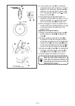
Page 19: ... pulled out from thread hole 3 Pass the thread through thread hole of the horn section and pull out the thread by 2 5 cm from the thread hole If the bobbin is installed in the bobbin case orienting the reverse direction the bobbin thread pulling out will result in an inconsistent state 4 7 Adjusting the thread tension 1 Needle thread tension Turn thread tension nut No 2 clockwise to increase or co...

Page 20: ...chine stops even when the thread does not break In the case of using thin thread the thread tension is too high the sewing machine runs at a low speed etc Turn the adjusting knob clockwise to in crease the sensitivity The sewing machine does not stop even when the thread breaks In the case of the sewing machine runs at a high speed etc Turn the adjusting knob counterclockwise to decrease the sensi...

Page 21: ...e up spring 1 For thread take up spring on the left side loosen screw and adjust the stroke of the spring by moving the screw along the slot for adjustment 2 For thread take up spring on the right side loosen screw and adjust the stroke of the spring by moving thread take up spring adjusting plate along thread take up spring base 2 When you want to change the tension of the thread take up spring 1...

Page 22: ...ng the IP 420 changeover of motion ON OFF is performed with key When the needle thread clamp device is OFF the machine automatically operates at slow start When memory switch No 35 is 1 prohibited the thread clamp does not work In addi tion key is ineffective 1 When with thread clamp motion use the sewing machine after adjusting the needle thread length at the start of sewing to 45 to 55 mm When t...

Page 23: ...ion is DAT Read from media Max 999 patterns can be used 2 There are two different ways to use the data M3 data of the AMS D Series on the AMS 221ENTS Reading by using IP 420 Use PC personal computer and copy file AMS AMS00xxx M3 of M3 from floppy disk of AMS D to AMS of media Insert the media to IP 420 and select Pattern No xxx from M3 data Changing to vector format data using PM 1 Change to the v...

Page 24: ...e the cover By closing the cover it is possible to access If the media and the cover come in contact with each other and the cover is not closed check the following matters Check that the media is securely pressed until it goes no further Check that the inserting direction of the media is proper 1 When the inserting direction is wrong panel or media may be damaged 2 Do not insert any item other th...

Page 25: ...mpletion of copying the data remove the USB device Remove the USB device Put the cover back in place Cautions when using the media Do not wet or touch it with wet hands Fire or electric shock will be caused Do not bend or apply strong force or shock to it Never perform disassembling or remodeling of it Do not put the metal to the contact part of it Data may be disappeared Avoid storing or using it...

Page 26: ...USB terminal on the IP panel until it will go no further Do not turn the power OFF while the data on the USB flash drive is being accessed USB specifications Conform to USB 1 1 standard Applicable devices 1 Storage devices such as USB memory USB hub FDD and card reader Not applicable devices CD drive DVD drive MO drive tape drive etc Format supported FD floppy disk FAT 12 Others USB memory etc FAT...

Page 27: ... screen can be performed COMMUNICATION key Changeover of the data input screen and the communication screen can be performed MODE key Changeover of the data input screen and the mode changeover screen which performs various detail settings can be performed Contrast control Brightness control CompactFlash TM eject button CompactFlash TM slot Cover detection switch Connector for external switch Conn...

Page 28: ...on This button scrolls the button or the display in the downward direction RESET button This button performs the release of error NUMERAL INPUT button This button displays ten keys and input of numerals can be performed CHARACTER INPUT button This button displays the character input screen Refer to II 2 18 Naming users pattern p 55 RESSER LOWERING button Presser is lowered and the presser lowering...

Page 29: ...ever the power is turned ON Select the pattern No you desire to sew When the power is turned ON the data input screen is dis played Pattern No button A whichs selected at present is displayed in the center of the screen Press the button to select the sewing shape For selecting procedure of the sewing shape refer to II 2 5 Performing sewing shape selection p 31 When READY key B is pressed the back ...

Page 30: ...g frame needle interferes with the feeding frame during sewing and there is a danger of needle breakage or the like 2 When the presser is going up be careful that your fingers are caught with the presser since the presser moves after coming down 3 When turning OFF the power without pressing READY key the set value of Pat tern No X enlargement reduction ratio Y enlargement reduction ratio Max sew i...

Page 31: ...creen is displayed Refer to II 2 17 Performing new register of users pattern p 54 C PATTERN BUTTON NAME SETTING button Pattern button name input screen is displayed Refer to II 2 18 Naming users pattern p 55 D THREAD CLAMP button Effective ineffective of thread clamp is selected Thread clamp ineffective Thread clamp effective E INTERMEDIATE PRESSER SETTING button Intermediate presser is lowered an...

Page 32: ...ed on this button When the scale input is set to non selection by setting memory switch the button goes out and the X scale is displayed Refer to II 2 6 Changing item data p 33 Actual size value in Y direction of sewing shape being selected at present is displayed When the actual size value input is selected by setting memory switch Y actual size value setting button is displayed Refer to II 2 6 C...

Page 33: ...er to the start of sewing and raises the presser at the time of temporary stop Kind and No of the sewing shape being selected at present is displayed There are 4 kinds below of the kinds of sewing shape Users pattern Vector format data M3 data Sewing standard format Be sure to use the media that has been formatted with IP 420 For the formatting procedure of the media refer to II 2 32 Performing fo...

Page 34: ...direction of sewing shape being selected is displayed N X ACTUAL SIZE VALUE display Actual size value in X direction of sewing shape being selected is displayed O Y ACTUAL SIZE VALUE display Actual size value in Y direction of sewing shape being selected is displayed P Y SCALE RATE display Scale rate in Y direction of sewing shape being selected is displayed Q MAX SPEED LIMITATION display Maximum ...

Page 35: ...of sewing shape There are 4 kinds below of the sewing shape Select the kind you desire from among them Pictograph Name Users pattern Vector format data M3 data Sewing standard format Maximum number of patterns 999 999 999 999 Select the sewing shape you desire from SEWING SHAPE SELECTION buttons E and press ENTER F button The sewing shape list screen corresponding to the kind of sewing shape you s...

Page 36: ...he sewing shape is determined and the data input screen is displayed When the sewing shape is users pattern the screen as A is displayed PATTERN NO SELECTION button J that is registered to users pattern is displayed Press the button of PATTERN NO you desire to select When VIEWER button K is pressed the shape of the pattern No selected is displayed and you can confirm it G I K A J H ...

Page 37: ...uction function mode enlargement and reduction can be performed with in crease decrease of pitch When X Y scale rate is individually set in case of circle or arc or X Y enlargement and reduction are repeated the sewing is changed to point sewing and the shape may not be kept Enlargement and reduction can be performed by increase decrease of pitch In this case set and read X Y scale rate in the pat...

Page 38: ...d since the reduction ratio is excessive ly small E045 Pattern data error is displayed 3 When the scale rate is changed with increase decrease of number of stitches pitch is fixed mechanical control command inputted to the points other than the shape point is deleted When X Y enlargement reduction ratio thread tension intermedi ate presser adding deleting of thread tension command or adding deleti...

Page 39: ...ure for inputting color change commands in pattern data During the automatic changeover mode automatic changeover mark C on the sewing screen When manual changeover mode B is selected needle changeover button when the right needle is selected when the left needle is selected D is displayed The needle used for sewing is changed over between the right and left needles every time the button is presse...

Page 40: ...ton while ignoring the color change commands in pattern data Refer to II 2 7 How to change the color change mode p 35 If you do not specify the needle used for sewing with color change commands the right needle is used for sewing Needle cannot be changed over unless the thread is trimmed The color change commands existing at some midpoints in sewing before thread trimming are disabled Color change...

Page 41: ...a and press the OK button Left click to select the first needle entry point A in the example of sewing elements for which the thread color is to be specified Then confirm the selection by clicking the right mouse button Selecting the thread color to be changed over The color change control command parame ter dialog is displayed Select the color to be changed and press the OK button Parameter 1 Sew...

Page 42: ... the left needle F sewing with the right needle G and press enter H Selecting the needle used for sewing A color change command is input A color change command is added to the top part of the sew ing elements you have selected When the needle used for sewing is changed the display color of the shape changes J section right needle Orange color left needle Light blue To change the color coding metho...

Page 43: ...ecified by the color change command can be checked by pressing information display button A at color change command position A B Sewing with the left needle sewing with the right needle C A B The needle used for sewing can also be checked by pressing information display button A on sewing element B C ...

Page 44: ... shape with color coded using the main unit input function B A Press setting button A C Select color change command C to display the pat tern shape with color coded according to the thread color Press display color select button B ...

Page 45: ...y moves to the sewing end position When the COMMAND SEARCH BACKWARD button F is pressed the feed automatically moves to the sew ing start position To stop the feed press button C D E F G or H When INTERMEDIATE PRESSER button G is pressed the intermediate presser is raised or lowered This button is not displayed when MEMORY switch is set at 0 zero Changeover of the needle is executed by moving the ...

Page 46: ...sewing can be started by depressing the foot switch before sewing shape checking is not completed 2 10 Performing modification of needle entry point 1 Editing the intermediate presser height Press STEP SEWING button A on the sewing screen to display the step sewing screen The sewing shape is displayed at the center of the screen The current point sewing start position and sewing end position are r...

Page 47: ...n H is pressed the work clamp moves to its origin and the screen is restored to the sewing screen When COMMAND DELETE button I is pressed the screen for deleting the command as shown in A is displayed When J is pressed the intermediate presser height increase decrease input screen is displayed Input a desired value on this screen using numeric keypad and keys K When ENTER button L is pressed the d...

Page 48: ...on B Press command retrieval forward button E or backward button F Then the needle entry point moves forward or backward from the current point to the one at which a color change command is found To stop the feed press button C D E F G or H When INTERMEDIATE PRESSER button G is pressed the intermediate presser is raised or lowered This button is not displayed when MEMORY switch U103 is set at 0 ze...

Page 49: ... is lowered Use the machine after lowering the presser 2 When the intermediate presser rests at its lower position the movement of the intermediate presser and needle differ depending on the setting of MEMORY switch 3 When increasing the height of intermediate presser or making the needle size thicker confirm the clearance between the wiper and the components Wiper cannot be used unless the cleara...

Page 50: ...IATE PRESSER UP DOWN button C FEED BACKWARD button D FEED FORWARD button E and RETURN TO ORIGIN button F are displayed in the screen 1 When the presser is raised and the operation is stopped on the way because of the trouble of forget ting to enter the bobbin case or the like press PRESS ER UP button G and turn OFF the power 2 PRESSER UP button G is not displayed when the presser is of pneumatic t...

Page 51: ...he operation is stopped on the way because of the trouble of for getting to enter the bobbin case or the like press PRESSER UP button G and turn OFF the pow er 2 PRESSER UP button G is not displayed when the presser is of pneumatic type Release the error Press RESET button A to release the error 2 To perform re sewing from the start Return to the origin When RETURN TO ORIGIN button F is pressed th...

Page 52: ...ng amount set can be effective only in the sewing screen When the screen returns to the input screen by press ing down READY key the moving amount set is erased Displaying the intermediate presser set ting screen or the presser down screen Press presser down button A or inter mediate presser setting button B on the data input screen or the sewing screen to display the intermediate presser setting ...

Page 53: ... Then the screen returns to the previous screen In the case such as after the completion of threading the thread end should be sucked for clamping Refer to I 4 4 Procedure for clamping the needle thread p 14 The thread suction button on the shape check screen is only enabled while the presser foot is lowered E F D C A B Turn OFF the power before threading the machine head Refer to I 4 3 How to nee...

Page 54: ...Press STOP button B and the sewing machine stops and returns to the normal mode Or depress the start pedal again during winding bobbin and the sewing machine stops while the bobbin thread winding mode stays as it is Depress the start pedal again and the bobbin winding starts again Use this way when winding bobbin thread around plural bobbins Bobbin winder does not work immediately after turning ON...

Page 55: ...e existing value is equal to the set value the count up screen is displayed DOWN counter Every time the sewing of one shape is performed the existing value is counted down When the existing value is reached to 0 the count up screen is displayed Counter disuse The sewing counter does not count a finished shape even when the machine has sewn the shape The counter screen of the sewing counter is not ...

Page 56: ...ut the set value When 0 is inputted in the set value the display of count up screen is not performed Bobbin counter UP counter The counter increases the existing value by one every time the machine has sewn 10 stitches When the existing value is equal to the set value the count up screen is displayed DOWN counter The counter decreases from the existing value by one every time the machine has sewn ...

Page 57: ... screen When you desire to revise the counter value during sewing work due to the mistake or the like press COUNTER VALUE CHANGE button A on the sewing screen The counter value change screen is displayed 2 Count up releasing procedure When the count up condition is reached during sewing work the count up screen is displayed and the buzzer beeps Press CLEAR button A to reset the counter and the scr...

Page 58: ...ng new register of users pattern Input the users pattern No Input the users pattern No you desire to newly register with the ten keys B It is possible to retrieve the users pattern No which has not been registered with the or button C and D Determine the users pattern No Press ENTER button E to determine the users pattern NO to be newly registered and the data input screen at the time of users pat...

Page 59: ...tton B you desire to input and the input of character can be performed As many as 255 characters to and to and symbols can be input The cursor can be moved with CURSOR LEFT TRAVEL button C and CURSOR RIGHT TRAVEL button D When you desire to delete the inputted character adjust the cursor to the position of the character you desire to delete and press DELETE button E Finish the input of character W...

Page 60: ...button No which has been already registered is prohibited It is possible to retrieve the pattern button No which has not been registered with the or button C and D Select the folder to be stored It is possible for the pattern buttons to be stored in five folders As many as 10 pattern buttons can be stored for one folder The folder to store the button can be selected with FOLDER SELECTION button E ...

Page 61: ... displayed D WINDING BOBBIN button Bobbin thread can be wound Refer to II 2 15 Winding bobbin thread p 50 E PATTERN BUTTON NO display Pattern button No being selected at present is displayed on this button and when the button is pressed the pattern button No selection screen is displayed Refer to II 2 21 Performing pattern button No selection p 61 F SEWING SHAPE The sewing shape of the currently s...

Page 62: ...ravel amount in Y direction which is registered to the pattern button No being selected is displayed M X ACTUAL SIZE VALUE display X actual size value which is registered to the pattern button No being selected is displayed N X SCALE RATE display X scale rate which is registered to the pattern button No being selected is displayed O Y ACTUAL SIZE VALUE display Y actual size value which is register...

Page 63: ...hich is registered to the pattern button No being selected is displayed E THREAD CLAMP button Effective ineffective of thread clamp is selected Thread clamp ineffective Thread clamp effective F INTERMEDIATE PRESSER SETTING button The intermediate presser is lowered and the intermediate presser reference value change screen is displayed Refer to II 2 6 Changing item data p 33 G RETURN TO ORIGIN but...

Page 64: ... is displayed Refer to II 2 16 Using counter p 51 Q COUNTER CHANGE OVER button The counter display can be changed over among the sewing counter No of pcs counter and bobbin counter Refer to II 2 16 Using counter p 51 R STEP SEWING button Step sewing screen is displayed Checking of the pattern shape can be performed Refer II 2 9 Checking pattern shape p 41 S FOLDER NO display Folder No in which the...

Page 65: ...pattern button No button C which have been registered are changed over in order The contents of sewing data which have been inputted in the pattern button No are displayed in the button Here press the pattern button No button C you desire to select Determine the pattern button No When ENTER button D is pressed the pattern button No selection screen is closed and the selection is finished However t...

Page 66: ...layed with every folder which is specified when the pattern is newly created When FOLDER SELECTION button B is pressed the pattern button to be displayed is changed Display and press the button of the pattern button No you desire to sew When it is pressed the pattern button No is selected WARNING Make sure without fail of the contour of the sewing pattern after selection of the sewing pattern If t...

Page 67: ...nd C Scale rate in Y direction can be changed to the actual size value input by selection of memory switch Max input range and initial value of max speed limitation E are determined with memory switch The input range of travel amount in X direction F and travel amount in Y direction G differs accord ing to the sewing range Display the input screen of the item data you desire to change Data that ca...

Page 68: ...f the sewing screen green press READY switch to display the data input screen blue Call the pattern copy screen When PATTERN BUTTON COPY button A is pressed the pattern button copy copy source selection screen is dis played Determine the change of item data For example input X scale rate Press B to display the item data input screen Input the value you desire with the ten keys or or key L When ENT...

Page 69: ...tion state returns to the pattern button copy copy source selection screen after ap proximately two seconds Combination data can be copied in the same way 2 24 Changing sewing mode Select the sewing mode When switch is pressed in the state that the pattern has been registered SEWING MODE SELECTION button A is displayed on the screen When this button is pressed the sewing mode changes alternately t...

Page 70: ...EGISTER button COMBINATION DATA COPY button COMBINATION DATA NAME INPUT button COMBINATION DATA NAME display PRESSER DOWN button BOBBIN WINDER button Description Combination data No new register screen is displayed Refer to II 2 19 Performing new register of pattern button p 56 Combination pattern No copy screen is displayed Refer to II 2 23 Copying pattern button p 64 Combination data name input ...

Page 71: ...etting of the skip of steps p 73 in II 2 26 Performing combination sewing p 70 As many as the number of inputted patterns is displayed in H and I display and button J NEXT PAGE DISPLAY button This button is displayed when the number of patterns registered to combination data has reached eight or more K UP SCROLL button The pattern No which is previous to the current one is selected L DOWN SCROLL b...

Page 72: ...screen is displayed To raise the presser press the presser up button displayed in the presser down screen This button returns the presser to the start of sewing and raises the presser when the present presser position is on the way of sewing Combination data No being selected is displayed Pattern button No being sewn is displayed The sewing shape of the currently selected pattern is displayed The ...

Page 73: ...ewn is displayed S SPEED variable resistor Number of revolutions of the sewing machine can be changed T Y ACTUAL SIZE AMOUNT display Actual Y size value of the sewing shape which is registered to the pattern button No being sewn is displayed U Y SCALE RATE display Y scale rate of the sewing shape which is registered to the pattern button No being sewn is displayed V MAX SPEED LIMITATION display Ma...

Page 74: ...in the upper part of the screen and other combination data No buttons which have been registered are displayed in the lower part of the screen Select the combination data No When UP DOWN button B is pressed combination data No buttons C which have been registered are changed over in order It is also possible to display the combination data No input screen using NUMBER INPUT button D and input a co...

Page 75: ...ine the pattern No When ENTER button E is pressed the pattern No se lection screen is closed and the selection is finished Repeat steps through as many as the number of pat tern Nos you desire to register When the first register is determined the second pattern selec tion button F is displayed Repeat steps through as many as the number of pattern Nos you desire to register When UP or DOWN SCROLL b...

Page 76: ...bination data including the step you desire to delete has been selected Display the pattern No selection screen Press UP DOWN SCROLL button A to bring the PATTERN SELECT button for the step to be deleted under the selected state B Then when STEP DELETE button C is pressed the data step delete popup window is dis played Performing deleting the step of the selected combination data When ENTER button...

Page 77: ...nction D E A B C Pressing the button of the step to be skipped Press button C of the step to display The step is set to Skip Another press on the button resets the skip setting It is possible to set two or more steps to Skip When all skip button D or all skip reset button E is pressed the skip can be set for all steps or the skip setting can be reset for all steps Note that the sewing screen is no...

Page 78: ...EN MODE SELECT button A is displayed on the screen When this button is pressed the screen mode is changed over between the nor mal operation and the simple operation When the normal operation is selected When the simple operation is selected A With IP 420 the SIMPLE OPERATION mode is available ...

Page 79: ... 75 2 28 LCD display when the simple operation is selected 1 Data input screen individual sewing User s pattern Media pattern Direct pattern B C E M F N O H I J P A L K D G Ⓐ Ⓑ A B F F Ⓒ ...

Page 80: ...elected edit item is displayed When no edit item is selected this display is not given H MAX SPEED LIMITATION SETTING button The current max speed limitation is indicated on the button When the button is pressed the max speed limitation can be changed During the setting procedure the max speed limitation is indicated on edit data display G The max speed limitation is increased decreased in increme...

Page 81: ...yed according to the setting of MEMORY switch Refer to II 2 6 Changing item data p 33 Ⓐ MEDIA PATTERN WRITE button Data on a media pattern is written When this button is pressed the new media pattern registration screen is displayed This button is displayed when the media pattern is selected Ⓑ USER S PATTERN WRITE button Data on a user s pattern is written When this button is pressed the new user ...

Page 82: ... 78 User s pattern Media pattern Direct pattern 2 Sewing screen individual sewing D A B C D M P O E F G H N R Q I J K L B C Ⓐ M A D D ...

Page 83: ... height reference value is indicated on the button When the button is pressed the intermediate presser height reference value can be set During the setting procedure the intermediate presser height reference value is indicated on edit data display H The intermediate presser height reference value is increased decreased in increments of 0 1 mm using PLUS button K or MINUS button L J SPEED CHANGE bu...

Page 84: ... being selected is displayed This display is given when a direct pattern is selected C TRAVEL AMOUNT IN Y DIRECTION display The amount of travel in the Y direction which is registered to the pattern button No being selected is displayed This display is given when a direct pattern is selected D Needle changeover mode display The needle changeover mode which is being selected at present is displayed...

Page 85: ...PATTERN No SETTING button Pattern No is set Registered pattern No is retrieved using PLUS button G and MINUS button H F PATTERN LIST button Pattern No and type which are currently selected are indicated on the button When the button is pressed the selected pattern list screen is displayed for the pattern selection G PLUS button The value for the selected item is increased in increments of the refe...

Page 86: ...ttern is displayed N X ACTUAL SIZE VALUE display The actual X size value of the currently selected pattern is displayed O Y ACTUAL SIZE VALUE display The actual Y size value of the currently selected pattern is displayed P TRAVEL AMOUNT IN X DIRECTION display The amount of travel in the X direction of the currently selected pattern is displayed Q TRAVEL AMOUNT IN Y DIRECTION display The amount of ...

Page 87: ... ADVANCE button The pattern to be sewn can be advanced to the next one F SHAPE CHECK button The shape of the pattern which is being selected is checked using PLUS button J or MINUS button K The current number of stitches is indicated on edit data display V Refer to II 2 21 Performing pattern button No selection p 61 G COUNTER VALUE CHANGE button The counter value is changed using PLUS button J or ...

Page 88: ...d with color coded according to the needle used for sewing The section which is sewn with the right needle Orange color The section which is sewn with the left needle Light blue Q NUMBER OF STITCHES display The number of stitches for the currently selected pattern is displayed R X ACTUAL SIZE VALUE display The actual X size value of the currently selected pattern is displayed S Y ACTUAL SIZE VALUE...

Page 89: ...to II 3 MEMORY SWITCH DATA LIST p 97 2 29 Changing memory switch data Display the memory switch data list screen When MODE key is pressed memory switch button A is displayed on the screen When this button is pressed the memory switch data list screen is displayed Select the memory switch button you desire to change Press UP DOWN SCROOL button C and select the data item button B you desire to chang...

Page 90: ...ion screen is displayed Display the maintenance and inspection information screen Press maintenance and inspection information screen display button B in the information screen Information on the following three items is displayed in the maintenance and inspection information screen Needle replacement 1 000 stitches Cleaning time hour Oil replacement time hour The interval to inform of the inspect...

Page 91: ...ive items are as follows Needle replacement A201 Cleaning time A202 Oil replacement time A203 For the grease up portion refer to the item of III 1 7 Replenishing the designated places with grease p 120 Perform clearing remaining time up to the replacement When button C of the item you desire to clear is pressed the time of replacement clear screen is displayed When CLEAR button F is pressed the re...

Page 92: ...the sewing machine In addition the function can upload the aforementioned data to the media or personal computer As the means of communication a media slot and USB port are prepared However SU 1 data server utility is necessary to perform download upload from the personal computer 1 Handling possible data Sewing data that can be handled are 4 kinds below and the respective data formats are as show...

Page 93: ...re four communication procedures as described below B Writing data from media to panel C Writing data from personal computer server to panel D Writing data from panel to media E Writing data from panel to personal computer server Select the button of communication procedure you desire Select the data No When F is pressed the writing file selection screen is displayed Input the file No of the data ...

Page 94: ...on A is pressed the data No plural selection screen is displayed Perform the data No selection Since the list of existing data file numbers is displayed press FILE NO button B you desire to write It is possible to invert the selected state of the button with INVERSION button C Determine the data No When ENTER button D is pressed the data No plural selection screen is closed and the data selection ...

Page 95: ...the during communication screen When performing writing to the pattern No which already exists the overwriting confirmation screen is displayed before writing When performing overwriting press ENTER button F When performing overwriting all without displaying the over writing confirmation screen press OVERWRITING button G in all cases F G ...

Page 96: ...ormatting Save necessary data in the media to the other media before formatting When formatting is performed the inside data are deleted When two or more media are connected to the sewing machine the medium to be formatted is determined by the predetermined priority order High Low CF TM slot USB device 1 USB device 2 When a CompactFlash TM is inserted in the CF TM slot the CompactFlash TM will be ...

Page 97: ...depress the start pedal without change and re start the sew ing If not press THREAD TRIM button B and perform thread trimming When performing thread trimming the feed forward back pop up is displayed Adjust the presser to the re sewing position Every time FEED BACK button C is pressed the press er returns by one stitch Every time FEED FORWARD button D is pressed the presser moves forward by one st...

Page 98: ...button A is pressed and the error is re leased the sewing screen is displayed Perform sewing work again from the start When the pedal is depressed sewing starts 3 When the rest switch is not displayed When a large slip is detected the reset switch is not displayed Turn OFF the power A ...

Page 99: ...2 34 Precautions to be taken when creating patterns Since the presser foot lift prohibition area is determined with reference to the set values of the feed movable range from K056 to K058 the area is affected if those set values are changed In the presser foot lift prohibition area shown in the figure below the presser foot cannot be lifted since the feeding frame and the needle thread suction dev...

Page 100: ...Enter a second origin inside the boundary line Move the current point on to the jump at the position where the presser foot can be lifted Then press code list button B B A C D Select No 002 Second origin function C from the code list and press enter button D The second origin command is inserted at the current point Then the presser foot will be on standby at this position until it is lifted ...

Page 101: ...0 Tension disk is floated 1 or more Tension disk is closed 0 to 200 1 Thread tension setting at the time of thread trimming 0 Tension disk is floated 1 or more Tension disk is closed 0 to 200 1 Thread tension changeover timing at the time of thread trimming 6 to 10 1 Sewing speed of 1st stitch In case of without thread clamp 200 to 1500 100 sti min Sewing speed of 2nd stitch In case of without thr...

Page 102: ...be performed every time after end of sewing other than combination sewing Without origin retrieval With origin retrieval Origin retrieval in combination sewing can be set Without origin retrieval Every time 1 pattern is finished State of presser when sewing machine stops by temporary stop command can be selected Presser rise Presser rise with presser switch Panel operating sound error Without buzz...

Page 103: ... shape size change can be selected input Actual size input Bend position of thread clamp is selected 0 S type 1 H type thin thread 50 to 8 2 H type intermediate 3 H type thick thread 5 to 2 Thread clamp and thread clamp position selection Front position Rear position Thread breakage detection selection Thread breakage detection invalid Thread breakage detection valid Number of invalid stitches at ...

Page 104: ...o right 13 to 99 Solid presser 1 When using these items refer to Engineer s Manual Feeding frame control midway stop time open close Operation order of feeding frame by pedal operation when lifting the feeding frame by the temporary stop command in the pattern data is set 0 to 99 1 0 Solid presser 1 Right left separated presser Without priority of right left 2 Right left separated presser In the o...

Page 105: ...lection of motion Without motion With motion Selection of needle upper dead point at the time of origin retrieval return to origin Without With Temporary stop thread trimming operation Automatic thread trimming Manual Thread trimming by turning Stop SW ON again Main motor X Y feed synchronized control speed pitch 2500 sti min 3 5mm 2200 sti min 3 5mm 1800 sti min 3 5mm 1400 sti min 3 5mm Increasin...

Page 106: ...eight p 16 0 to 7 0mm 0 1 With without needle cooler control Without With The time to automatically exit from the count up screen can be set 0 99 1 Selection of needle upper dead point at the time of origin retrieval return to origin Without With Grease up error Clearing of number of stitches of grease up is performed Refer to III 1 7 Replenishing the designated places with grease p 120 Color chan...

Page 107: ...eed of 4th stitch In case of without thread clamp 1500 Sewing speed of 5th stitch In case of without thread clamp 2000 Thread tension of 1st stitch In case of without thread clamp 0 Thread tension changeover timing at the time of sewing start In case of without thread clamp 5 Counter motion selection Height of eight of presser at the time of 2 step stroke 70 Buzzer sound can be prohibited Number o...

Page 108: ...h Pedal SW2 with without latch Pedal SW3 with without latch Pedal SW4 with without latch Enlarging reducing function mode Jog move function mode Retainer compensation motion selection of motion Selection of needle upper dead point at the time of origin retrieval return to origin Temporary stop thread trimming operation Main motor X Y feed synchronized control speed pitch Intermediate presser with ...

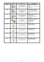
Page 109: ... reset Previous screen E012 Read error Data read from external media cannot be performed Possible to re start after reset Previous screen E013 Write error Data write from external media cannot be performed Possible to re start after reset Previous screen E015 Format error Format cannot be performed Possible to re start after reset Previous screen E016 External media capacity over Capacity of exter...

Page 110: ...edle bar to its predetermined position Data input screen E031 Air pressure drop Air pressure is dropped Possible to re start after reset Data input screen E032 File interchanging error File cannot be read Possible to re start after reset Data input screen E040 Sewing area over Possible to re start after reset Sewing screen E043 Enlarging error Sewing pitch exceeds Max pitch Possible to re start af...

Page 111: ...nput screen E221 Grease up error At the time of operation of 120 million stitches The sewing machine is put in the sewing impossible status It is possible to clear with memoryswitch Refer to III 1 7 Replenishing the designated places with grease p 120 Possible to re start after reset Data input screen E302 Head tilt confirmation When head tilt sensor is OFF Possible to re start after reset Previou...

Page 112: ...h error Possible to re start after reset Password input screen E703 Panel is connected to the sewing machine which is not supposed Machine type error When the machine type code of system is not proper in the initial communication Possible to rewrite program after pressing down communication switch Communi cation screen E704 Inconsistency of system version System software version is inconsistent in...

Page 113: ...olenoid power of SERVO CONTROL p c b fluctuates more than 15 Turn OFF the power E905 Heat sink temperature for SERVO CONTROL p c b abnormality Turn ON the power again after taking overheat time of SERVO CONTROL p c b Turn OFF the power E907 X feed motor origin retrieval error When origin sensor signal is not inputted at the time of origin retrieval motion Turn OFF the power E908 Y feed motor origi...

Page 114: ...reset E918 MAIN p c b overheat Overheat of MAIN p c b Turn ON the power again after taking time Turn OFF the power E925 Intermediate presser motor origin retrieval error Origin sensor of intermediate presser motor does not change at the time of origin retrieval Turn OFF the power E926 X motor position slip error 1 In case of error display during sewing Possible to re start after reset 2 In case of...

Page 115: ...rn OFF the power E932 Y motor overload error Turn OFF the power E933 Thread trimming motor overload error Turn OFF the power E935 Intermediate presser motor overload error Turn OFF the power E936 X Y motor out of range error Turn OFF the power E943 MAIN CONTROL p c b trouble When data writing to MAIN CONTROL p c b cannot be performed Turn OFF the power E946 HEAD RELAY p c b trouble When data writi...

Page 116: ...iting confirmation of media Overwriting is performed OK M530 Overwriting confirmation of vector data of panel M3 data sewing standard format data simplified program data Overwriting is performed OK M531 Overwriting confirmation of vector data of media M3 data sewing standard format data simplified program data Overwriting is performed OK M532 Overwriting confirmation of vector data on personal com...

Page 117: ... OK M544 Data corresponding to panel does not exist Data does not exist M545 Data corresponding to media does not exist Data does not exist M546 Data corresponding to personal computer does not exist Data does not exist M547 Overwriting prohibition on pattern data Overwriting cannot be performed since data exists M548 Overwriting prohibition on media data Overwriting cannot be performed since data...

Page 118: ... broken Initialization is performed OK M556 Initialization confirmation of customized data Customized key lock data is initialized OK M557 Confirmation of clearance of password setting Clears password Yes or no M653 During formatting Formatting is performed M669 During data reading Data is being read M670 During data writing Data is being written M671 During data converting Data is being converted...

Page 119: ...wing machine 2 Loosen setscrew in the driver Drawing bobbin case opening lever hook toward you open it to the right and left until bobbin case opening lever comes off At this time be careful not to let shut tle come off and fall 1 Use the left needle for adjustment 2 In the case the right and left needles differ in the count use the thinner one as the left needle and carry out adjustment 0 mm 0 mm...

Page 120: ...of driver Adjustment of height of driver 1 Adjust so that the blade point of inner hook meets the center of needle and tighten set screw 2 Bend the needle guard section of driver in the direction of arrow A so that the protruding amount from the bottom end of the needle guard section of driver to the tip of needle is 0 to 0 5 mm when the blade point of inner hook is out by 0 5 mm from the right en...

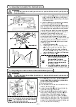
Page 121: ...the feeding frame still interferes with the face plate bearing and the feeding frame height does not change after the adjustment of the position of work clamp link adjust the pressure applied to the face plate bearing to lower it as far as no lateral play of the feeding frame occur At the time of delivery work clamp foot has been moved up and down to adjust the torque sliding torque of face plate ...

Page 122: ...2 mm is provided between the wiper and the suc tion mouth Adjustment of the forward travel position of the wiper 1 Vertical clearance between the top end of the wiper and the needle tip moving needle side when the former passes the latter Adjust to 1 to 3 mm 2 Clearance between the top end of the wiper and the needle moving needle side when the wiper travels forward until it will go no further Hor...

Page 123: ...l to verify that a clearance of 0 5 mm or more is provid ed between the top end of moving knife and the top end of needle thread clamp If a clearance of 0 5 mm or more cannot be secured adjust the position of moving knife within 18 5 0 5 mm to secure the specified clearance 0 5 mm or more 1 6 Needle thread clamp device When thread is caught at top end of the thread clamp thread clamp becomes incom...

Page 124: ...rther for a certain period of time without replenishing the places with grease after the display of error No E220 error E221 Grease up error is displayed and the sewing machine fails to operate since the error cannot be released even when the RESET key is pressed When error E221 Grease up error is displayed be sure to replen ish the designated places below with grease Then call the memory switch p...

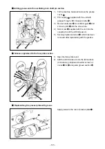
Page 125: ... shaft 3 Apply JUKI Grease A also onto the felt sur face of grease cover 1 Location where exclusive grease is provided The exclusive joint and setscrew for JUKI grease A are mounted at the location shown in the fi gure In addition exclusive grease for the LM guide is supplied with the unit as an accessory Add grease pe riodically when the grease runout warning No E220 is displayed on the panel or ...

Page 126: ...rease A onto periphery of inter mediate presser bar Remove setscrew from the intermediate presser bar bushing grease hole Put JUKI Grease A through inlet Tighten screw to fill inside the bushing with JUKI Grease A 4 Apply JUKI grease A to the surface of inter mediate presser spring Adding grease onto the eccentric cam section 1 Open crank rod cover 2 Remove setscrew from the grease inlet cover loc...

Page 127: ...coupling to add the JUKI Grease A 5 Securely tighten setscrew which has been removed after replenishing with the grease Adding grease onto the oscillating rock shaft pin section 1 Open the face plate cover 2 Add the JUKI Grease A onto the felt sections 4 locations peripheral shoulder screw ful crums to and guide groove section Grease supplement to the face plate section Replenishing the presser pl...

Page 128: ...LM guide 3 Points to be applied with the exclusive grease for the LM guide 1 If the grease has decreased due to cleaning air blow or other reasons apply grease again without excep tions 2 Do not apply the machine oil to the LM guide The grease inside the LM guide will flow out to cause the LM guide abrasion 3 When removing X travel bottom cover take care not to break the stopper rubber which is st...

Page 129: ...me lag fuse For solenoid and pulse motor power supply protection 3 15A time lag fuse For control power supply protection 2A fast blow type fuse 1 Loosen setscrew and remove setscrew 2 When screwing in adjustment screw the amount of oil of oil pipe left can be reduced 3 After the adjustment screw in setscrew and fix it 1 The state of standard delivery is the po sition where is lightly screwed in an...

Page 130: ... cord to the power plug as shown in the figure Caution Securely perform the insulation treatment to the red terminal which is not used with insulation tape or the like When the insulation is insufficient there is a danger of electric shock or leakage current C In case of using with single phase 200V to 240V Changing the changeover connector Connect to 200V the 100 200V changeover connector of FLT ...

Page 131: ...a fine whetstone or buff The needle hole guide has scratches Buff or replace it The needle strikes the intermediate presser foot Correct the position of the intermediate presser foot 16 Fibrous dust is in the groove of the shuttle race Take out the shuttle and remove the fibrous dust from the shuttle race The needle thread tension is too high Reduce the needle thread tension 15 The tension of the ...

Page 132: ...ial Stitch skipping at the 1st stitch Adjust the hook timing faster by a 1 2 stitch Intermediate presser is not properly positioned in terms of the needle Adjust the eccentricity between intermediate presser and needle so that needle enters in the center of intermediate presser 8 Threads break at time of thread trimming The moving knife has been improperly position Correct the position of the movi...

Page 133: ... thin thread the thread tension is too high or the sewing machine runs at a low speed Turn the sensitivity adjusting knob of the thread breakage detection sensor clockwise to increase the sensitivity 16 16 The thread breakage detection error does not occur and the sewing machine does not stop though the thread breaks The sensitivity of the thread breakage detection sensor is too high This problem ...

Page 134: ...ize Part No Size øA øB H L 14 to 20 40140277 φ1 8 φ2 9 7 5 37 1 H type installed needle DP X 17 18 OP means the optional H L φA φB Part No Application 40141947 The felt thread guide is used to replace the thread guide 40141946 when applying silicon oil to the needle thread The felt thread guide should be used in the case thread is likely to breaks due to the needle which has become hot or in order...

Page 135: ...Bar code reader Bar code function is a function to read the bar code and to switch to the corresponding sewing pattern for the applications such as the cassette identification etc By reading the bar code switching to 999 user patterns stored in the sewing machine memory and to 50 sewing data registered in the pattern button can be made To use this function AMS EN bar code option 40089238 will be r...

Reviews: