background image

– 101 –

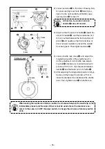
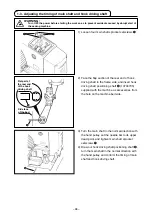
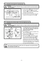
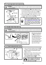
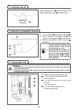
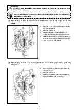
 1-13. replenishing the designated places with grease

C

B

C

B

A

C

D


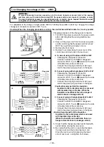
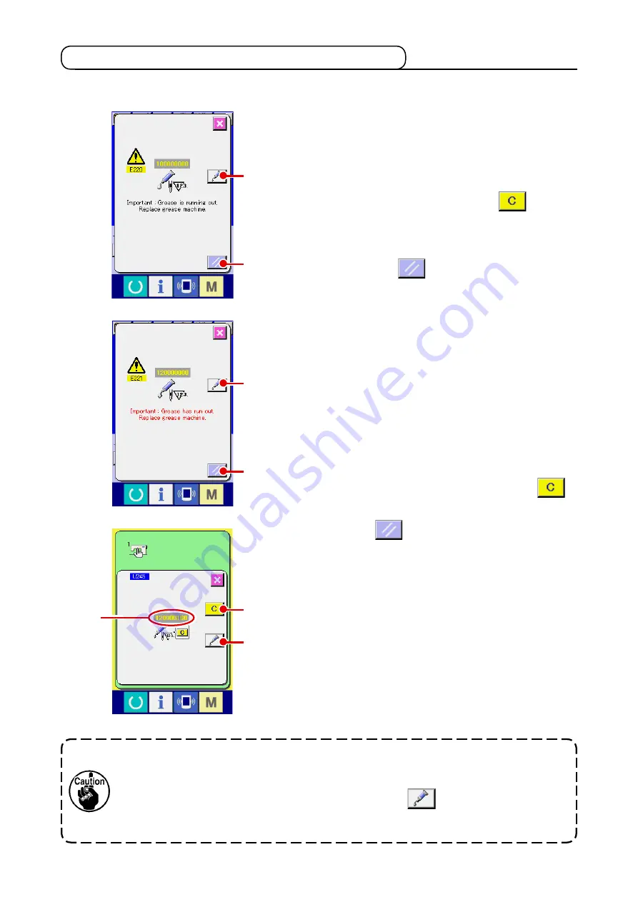
*   Perform grease supplement when the errors below are displayed or once a year (either one 

which is earlier). 

When the sewng machne has been used for a certan 
number of sttches, error "E220 Grease-up warnng" s 
dsplayed. Ths dsplay nforms the operator of  the tme of 
replenshng the desgnated places wth grease. Be sure to 
replensh the places wth the grease below. Then call the 
memory swtch U245, press CLEAR button 


A

 and 

set NUMBER OF STITCHES 

D

 to "0".

Even after the dsplay of the error "E220 Grease-up warn-
ng", when RESET key 


B

 s pressed, the error s re-

leased, and the sewng machne can be contnuously used. 
Afterwards, however, error code "E220 Grease-up warnng" 
s dsplayed every tme the power s re-turnng ON.
In addton, when the sewng machne s used further for a 
certan perod of tme wthout replenshng the places wth 
grease after the dsplay of error No. E220, error "E221 
Grease-up error" s dsplayed and the sewng machne fals 
to operate snce the error cannot be released even when 
the RESET key s pressed. 

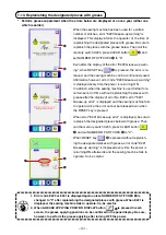
When error "E221 Grease-up error" s dsplayed, be sure to 
replensh the desgnated places below wth grease. Then 
call the memory swtch U245, press CLEAR button 


A

 and set NUMBER OF STITCHES 

D

 to "0".

When RESET key 


B

 s pressed wthout replensh-

ng the desgnated places wth grease, error code "E221 
Grease-up warnng" s dsplayed every tme the power s 
re-turnng ON afterwards and the sewng machne fals to 
operate. So, be careful.


1.  Error code E220 or E221 is displayed again unless NuMBEr oF StItcHES 

D

 is 

changed to "0" after replenishing the designated places with grease. When E221 is 

displayed, the sewing machine fails to operate. So, be careful.


2.  When GrEaSE aPPLYING PoSItIoN DISPLaY button 


C

 is pressed in each 

screen, the grease applying position can be confirmed in the panel display. Be sure, 

however, to perform the grease applying after turning oFF the power.

Summary of Contents for AMS-224E/IP-410

Page 1: ... ENGLISH Instruction Manual AMS 224E IP 410 CompactFlash TM is the registered trademark of SanDisk Corporation U S A ...

Page 2: ...read clamp device 13 5 3 How to use the plastic blank supplied with the machine as an accessory 14 OPERATION SECTION WITH REGARD TO THE PANEL 15 1 PREFACE 15 2 WHEN USING IP 410 18 2 1 Name of each section of IP 410 18 2 2 Buttons to be used in common 19 2 3 Basic operation of IP 410 20 2 4 LCD display section at the time of sewing shape selection 21 1 Sewing shape data input screen 21 2 Sewing sc...

Page 3: ...ng procedure of the combination data 56 4 Deleting procedure of the step of the combination data 56 2 23 Changing memory switch data 57 2 24 Using information 58 1 Observing the maintenance and inspection information 58 2 Releasing procedure of the warning 59 3 Observing the production control information 60 4 Performing setting of the production control information 61 5 Observing the working meas...

Page 4: ...e and counter knife 98 1 7 Needle thread clamp device 98 1 8 Thread breakage detector plate 98 1 9 Draining waste oil 99 1 10 Amount of oil supplied to the hook 99 1 11 Replacing the fuse 99 1 12 Changing the voltage of 100 200V 100 1 13 Replenishing the designated places with grease 101 1 Replenishing the face plate section felt intermediate presser link hinge screw with grease 102 2 Replenishing...

Page 5: ...n is selected 17 Max sewing speed limitation 200 to 2 500 sti min Scale 100 sti min steps 18 Pattern selection facility Pattern No selection method 19 Bobbin thread counter UP DOWN method 0 to 9 999 20 Sewing counter UP DOWN method 0 to 9 999 21 Memory back up In case of a power interruption the pattern being used will automatically be stored in memory 22 2nd origin setting facility Using jog keys...

Page 6: ...or 2 CONFIGURATION 1 Machine head 2 Wiper switch 3 Temporary stop switch 4 Feeding frame 5 Intermediate presser 6 Thread stand 7 Operation panel IP 410 8 Power switch 9 Control box 0 Foot pedal 1 2 3 4 6 7 9 0 5 8 ...

Page 7: ...nd lower plate 1 2 Temporarily fix throat plate auxiliary cover asm 3 with throat plate auxiliary cover support set screws 5 and washers 4 3 Temporarily fix throat plate auxiliary cover support 6 to the machine bed with setscrews M6 7 4 Fix throat plate auxiliary cover asm 3 on the machine bed with two counter sunk screws 8 5 Insert spacer 2 between cloth feed base cover 0 and throat plate auxilia...

Page 8: ...djustment Only for 6030 For the 6030 the table has been retracted from the normal position in the factory in prior to shipment After unpacking be sure to carry out the following steps 1 through 9 Position adjustment for the left table L is described as an example Adjust the position of the right table R in the similar manner Accessories to be used A Table fixing bolt cover HX00326000B x 2 B Power ...

Page 9: ...t two loca tions from the table stand side 5 Tighten screws 1 and 2 to mount the cover If the cover and tapped hole do not align align them by moving the table Tighten screw 2 after mounting the nut from the underside of the table 6 Securely tighten the table fixing bolts at two locations from the table stand side For refer ence Tightening torque 6 N m 7 After mounting the cover attach the table f...

Page 10: ...e cover or head grip does not interfere with it since breakage of the panel will be caused 1 Installing the IP 410 2 Installing the IP 410 guide 4 3 1 2 1 2 3 5 m m 5 m m 1 Install IP 410 2 almost in the center of opera tion box installing plate 1 2 Take a clearance of approximate 5 mm on both ends of right and left sides of IP 410 2 and fix IP 410 guide 3 with two screws 4 Do not place the positi...

Page 11: ...of air pressure Open air cock 1 pull up and turn air adjust ment knob 2 and adjust so that air pressure indicates 0 5 to 0 55 MPa Max 0 55 MPa Then lower the knob and fix it Close air cock 1 to expel air 3 6 Installing the eye protection cover WARNING Be sure to attach this cover to protect the eyes from the disperse of needle breakage Use eye protection cover 1 after securely attach ing it on fac...

Page 12: ...rt the claw of forklift up to the transverse beam A in front of the upper stand from the position as shown in the figure in the rear of the sewing machine 2 Lift the claw of the forklift up to the position where the claw of forklift comes in contact with the bot tom surface of the upper stand and the upper stand does not fall Take care not to allow the forklift claw to crush the cable Regulating g...

Page 13: ...Do not put your foot or climb on the sewing machine table or table stand during lubrica tion 2 Apply one drop of oil to the hook race 1 part to spread on it The oil tank to lubricate is for lubricating to the hook portion and the gear box portion For the hook portion the oil amount can be decreased when the number of revolutions used is low and the oil amount is large Refer to 1 10 Amount of oil s...

Page 14: ... 1 3 2 Threading of L type thread guide in case of large return of twist 4 5 Installing the bobbin WARNING Turn OFF the power before starting the work so as to prevent accidents caused by abrupt start of the sewing machine 1 Set the bobbin 1 into bobbin case 2 in the direction shown in the figure 2 Pass the thread through thread slit 3 of bobbin case 2 and pull the thread as it is By so doing the ...

Page 15: ...rmediate presser height Press INTERMEDIATE PRESSER SET TING button A and adjust with TEN keys B so that the clearance between the bot tom end of intermediate presser and the cloth is 0 5 mm thickness of thread used 1 Setting range of the intermediate presser is up to the standard of 3 5 mm However the setting range can be changed up to max 7 mm with memory switch U112 2 When increasing the height ...

Page 16: ...he pressure Decrease Increase 5 OPERATION OF THE SEWING MACHINE A B C 1 2 3 5 1 Sewing In case of the mechanical valve pedal 1 Set a workpiece under the feeding frame and depress pedal A of the pedal switch Then the feeding frame comes down When the foot is detached the feeding frame returns to its home position The lowering speed of the feeding frame changes according to the depressing amount Thi...

Page 17: ...ediate 20 to 5 3 Thick thread 5 to 2 Front standard or Rear Regarding thread clamp unit Change the set value of memory switch U69 according to the thickness of needle thread The value has been set to 1 Thin thread at the time of delivery Commendable value is Set value 1 for thread count 50 to 8 Set value 2 for thread count 20 to 5 and Set value 3 for thread count 5 to 2 The value will change in ac...

Page 18: ... 4530 6030 1 Plastic blank 40072147 40074148 2 Feeding frame 40072138 40072139 3 Setscrew SM1041401SC SM1041401SC 4 Washer WP0430801SC WP0430801SC 5 Nut NM6040001SC NM6040001SC 6 Positioning screw SM4040501SN SM4040501SN 5 4 2 1 6 3 When needle thread is excessively long at the time of using the thick thread the end of nee dle thread held with the needle thread clamp is rolled in the seams and sli...

Page 19: ...ax 999 patterns can be used 2 Using the data M3 data of AMS D series with AMS 224E There are two ways to use M3 data with AMS 224E 1 Reading by using IP 410 Use PC personal computer and copy file AMS AMS00xxx M3 of M3 from floppy disk of AMS D to AMS of media Insert the media to IP 410 and select Pattern No xxx from M3 data 2 Changing to vector format data using PM 1 Change to the vector format da...

Page 20: ...not stored in the folders above cannot be read So be careful Media drive SDATA Store sewing standard data SD00 DAT SD00 DAT AMS Store M3 data AMS00 M3 AMS00 M3 VDATA VD00 VDT Store vector format data VD00 VDT Vector format data Store in VDATA M3 data Store in AMS Sewing standard format Store in SDATA ...

Page 21: ...ome in contact with each other and the cover is not closed check the following matters Check that the media is securely pressed until it goes no further Check that the inserting direction of the media is proper 5 Removing procedure of the media 1 Hold the panel by hand open the cover and press the media removing lever The media is eject When the lever is strongly pressed the media may be broken by...

Page 22: ...erformed 4 COMMUNICATION key Changeover of the data input screen and the communication screen can be performed 5 MODE key Changeover of the data input screen and the mode changeover screen which performs various detail settings can be performed 6 Media slot Close the cover for use 7 Connector for RS 232C communication 8 Variable resistor for color LCD screen contrast adjustment 9 Connector for ext...

Page 23: ...utton This button scrolls the button or the display in the downward direction RESET button This button performs the release of error NUMERAL INPUT button This button displays ten keys and input of numerals can be performed CHARACTER INPUT button This button displays the character input screen Refer to 2 14 Naming users pattern p 39 RESSER LOWERING button Presser is lowered and the presser lowering...

Page 24: ...ed Set the language you use It is possible to change with Memory switch U500 When ending the selection screen with CANCEL but ton or ENTER button without performing the language selection the language selection screen is displayed when the power is turned ON next 2 3 Basic operation of IP 410 A B 2 Select the pattern No you desire to sew When the power is turned ON the data input screen is dis pla...

Page 25: ...n new register screen is displayed Refer to 2 13 Performing new register of users pattern p 38 Pattern button name input screen is displayed Refer to 2 14 Naming users pattern p 39 Effective ineffective of thread clamp is selected Thread clamp ineffective Thread clamp effective Intermediate presser is lowered and the intermediate presser reference value change screen is displayed Refer to 2 6 Chan...

Page 26: ... value setting button is displayed Refer to 2 6 Changing item data p 27 Scale rate in X direction of sewing shape being selected at present is displayed on this button When the scale input is set to non selection by setting memory switch the button goes out and the X scale is displayed Refer to 2 6 Changing item data p 27 Actual size value in Y direction of sewing shape being selected at present i...

Page 27: ...use of interruption of needle tip p 34 Effective ineffective of the thread clamp is selected Thread clamp ineffective Thread clamp effective Intermediate presser is lowered and the intermediate presser reference value change screen is displayed Refer to 2 6 Changing item data p 27 This button returns the presser to the start of sewing and raises the presser when the present presser position is on ...

Page 28: ...t is displayed Displayed only when the sewing shape being selected is the standard pattern Existing counter value is displayed on this button When the button is pressed the counter value change screen is displayed Refer to 2 12 Using counter p 35 Display of sewing counter No of pcs counter can be changed over Refer to 2 12 Using counter p 35 Step sewing screen is displayed Checking of the pattern ...

Page 29: ...d of sewing shape There are 4 kinds below of the sewing shape Select the kind you desire from among them Pictograph Name Users pattern Vector format data M3 data Sewing standard format Maximum number of patterns 200 999 999 999 Select the sewing shape kind you desire from SEWING SHAPE KIND SELECTION buttons E and press ENTER button F The sewing shape list screen corresponding to the kind of sewing...

Page 30: ...en ENTER button I is pressed the sewing shape is determined and the data input screen is displayed When the sewing shape is users pattern the screen as A is displayed PATTERN NO SELECTION button J that is registered to us ers pattern is displayed Press the button of PATTERN NO you desire to select A When VIEWER button K is pressed the shape of the pattern No selected is displayed and you can confi...

Page 31: ...tion mode enlargement and reduction can be performed with in crease decrease of pitch When X Y scale rate is individually set in case of circle or arc or X Y enlargement reduction are repeated the sewing is changed to point sewing and the shape may not be kept Enlargement reduction can be performed by increase decrease of pitch In this case set and read X Y scale rate in the pattern list screen Ma...

Page 32: ...3 When the scale rate is changed with increase decrease of number of stitches pitch is fixed mechanical control command inputted to the points other than the shape point is deleted H I In case of change display H the change confirmation screen is displayed at the time of the change of pattern When ENTER button I is pressed the information on the current pattern is invalidated and the pattern No is...

Page 33: ...s pressed the screen returns to the sewing screen When the checking of the shape is not in the position of the start of sewing or that of the end of sew ing press the pedal switch Then it is possible to sew from the midway of checking The sewing machine does not start even when the pedal switch is depressed with this mode 2 Display the step sewing screen When STEP SEWING button B is pressed the st...

Page 34: ...nsion command in the front or rear When you desire to stop press STOP button H Press ORIGIN MOVE button I and the needle moves to the start of sewing position The value which is displayed is the absolute value thread tension value thread tension command value Input the value you desire with TEN keys and keys J When ENTER button K is pressed the data is deter mined Thread tension value and intermed...

Page 35: ... When you desire to stop press STOP button H Press ORIGIN MOVE button I and the needle moves to the start of sewing position The value which is displayed is the absolute value intermediate presser height value intermediate presser increase decrease value Input the value you desire with TEN keys and keys J When ENTER button K is pressed the data is deter mined 1 When checking the needle or performi...

Page 36: ...on B to perform thread trimming When thread trimming is performed INTERMEDIATE PRESSER UP DOWN button C FEED BACKWARD button D FEED FORWARD button E and RETURN TO ORIGIN button F are displayed in the screen 2 9 How to use temporary stop A B C E F D 3 Adjust the presser to the re sewing position When FEED BACK button D is pressed the presser returns stitch by stitch and when FEED FORWARD button E i...

Page 37: ...rns to the start of sewing and the presser goes up 4 Perform again the sewing work from the start By the pedal operation the presser can be lowered and the start can be performed 2 Perform thread trimming Press THREAD TRIM button B to perform thread trim ming When thread trimming is performed INTERMEDIATE PRESSER UP DOWN button C FEED BACKWARD button D FEED FORWARD button E and RETURN TO ORIGIN bu...

Page 38: ...hen PATTERN BUTTON MOVE button A is pressed the pattern button move screen is displayed 2 10 When setting of sewing product is difficult because of interruption of needle tip A 2 Move the pattern Lower the presser and input the move direction with DIREC TION key B The moving amount set can be effective only in the sew ing screen When the screen returns to the input screen by press ing down READY k...

Page 39: ...his way when winding bobbin thread around plural bobbins Bobbin winder does not work immediately after turning OFF the power or immediately after moving from the main unit input Perform winding after setting pattern No or the like once pressing the READY key and displaying the sewing screen A B 1 Setting procedure of the counter 1 Display the counter setting screen Press switch and the COUNTER SET...

Page 40: ... one combination sewing is performed the existing value is counted up When the existing value is equal to the set value the count up screen is displayed DOWN counter Every time one combination sewing is performed the existing value is counted down When the existing value is reached to 0 the count up screen is displayed 3 Change of counter set value In case of the sewing counter press button D and ...

Page 41: ... existing value input screen is displayed Here input the existing value F G 2 Count up releasing procedure When the count up condition is reached during sewing work the count up screen is displayed and the buzzer beeps Press CLEAR button A to reset the counter and the screen returns to the sewing screen Then the counter starts counting again A ...

Page 42: ...r value during sewing work due to the mistake or the like press COUNTER VALUE CHANGE button A on the sewing screen The counter value change screen is displayed A D B C 2 Call the new register of users pattern screen Press NEW REGISTER button A and the new register of users pattern screen is displayed 2 13 Performing new register of users pattern A 1 Display the data input screen Only in case of th...

Page 43: ...ewing screen green press READY switch to display the data input screen blue 2 Call the character input screen When CHARACTER INPUT button A is pressed the character input screen is displayed 2 14 Naming users pattern 3 Input the character Press CHARACTER button B you desire to input and the input of character can be performed As many as 14 characters of characters to and to and symbols and can be ...

Page 44: ... button No which has been already registered is prohibited It is possible to retrieve the pattern button No which has not been registered with the or button C and D 4 Select the folder to be stored It is possible for the pattern buttons to be stored in five folders As many as 10 pattern buttons can be stored for one folder The folder to store the button can be selected with FOLDER SELECTION button...

Page 45: ...g users pattern p 39 Character which is registered to the pattern button No being selected is displayed Bobbin thread can be wound Refer to 2 11 Winding bobbin thread p 34 Pattern button No being selected at present is displayed on this button and when the button is pressed the pattern button No selection screen is displayed Refer to 2 17 Performing pattern button No selection p 45 Sewing shape wh...

Page 46: ... being selected is displayed Thread tension value which is registered to the pattern button No being selected is displayed Travel amount in X direction which is registered to the pattern button No being selected is displayed Travel amount in Y direction which is registered to the pattern button No being selected is displayed X actual size value which is registered to the pattern button No being se...

Page 47: ...ng sewing is displayed Character which is registered to the pattern button No being sewn is displayed Scale rate in X direction which is registered to the pattern button No being sewn is displayed Actual size value in X direction which is registered to the pattern button No being sewn is displayed Effective ineffective of thread clamp is selected Thread clamp ineffective Thread clamp effective W S...

Page 48: ...hich is registered to the pattern button No being sewn is displayed Total number of stitches of sewing shape which is registered to the pattern button No being sewn is displayed Needle thread tension value which is set to the pattern data being selected at present is displayed on this button and when the button is pressed the item data change screen is displayed Refer to 2 6 Changing item data p 2...

Page 49: ...on No When UP or DOWN SCROLL button B is pressed pattern button No buttons C which have been registered are changed over in order The contents of sewing data which have been inputted in the pattern button No are displayed in the button Here press the pattern button No button C you desire to select 4 Determine the pattern button No When ENTER button D is pressed the pattern button No selection scre...

Page 50: ...splayed with every folder which is specified when the pattern is newly created When FOLDER SELECTION button B is pressed the pattern button to be displayed is changed Display and press the button of the pattern button No you desire to sew When it is pressed the pattern button No is selected WARNING Make sure without fail of the contour of the sewing pattern after selection of the sewing pattern If...

Page 51: ... changed to the actual size value input by selection of memory switch Max input range and initial value of max speed limitation D are determined with memory switch The input range of travel amount in X direction F and travel amount in Y direction G differs accord ing to the sewing range 3 Display the input screen of the item data you desire to change Data that can be changed are 11 items below A H...

Page 52: ...he sew ing screen green press READY switch to display the data input screen blue 2 Call the pattern copy screen When PATTERN BUTTON COPY button A is pressed the pattern button copy copy source selection screen is dis played 4 Determine the change of item data For example input X scale rate Press B to display the item data input screen Input the value you desire with the ten keys or or key K When E...

Page 53: ...ection state returns to the pattern button copy copy source selection screen after ap proximately two seconds Combination data can be copied in the same way 2 20 Changing sewing mode 1 Select the sewing mode When switch is pressed in the state that the pattern has been registered SEWING MODE SELECTION button A is displayed on the screen When this button is pressed the sewing mode changes alternate...

Page 54: ...ON DATA NEW REGISTER button COMBINATION DATA COPY button COMBINATION DATA NAME INPUT button COMBINATION DATA NAME display PRESSER DOWN button BOBBIN WINDING Description Combination data No new register screen is displayed Refer to 2 15 Performing new register of pattern button p 40 Combination pattern No copy screen is displayed Refer to 2 19 Copying pattern button p 48 Combination data name input...

Page 55: ...screen is displayed Sewing order of the inputted pattern data is displayed When the screen is changed over to the sewing screen the pattern which is sewn first is displayed in blue color Numbers and types of patterns registered in H SEWING ORDER are displayed above the button When the button is pressed the pattern selection screen is displayed When the patterns which are registered to the combinat...

Page 56: ...neffective Thread clamp effective Presser can be lowered and the presser down screen is displayed To raise the presser press the presser up button displayed in the presser down screen This button returns the presser to the start of sewing and raises the presser when the present presser position is on the way of sewing Combination data No being selected is displayed Pattern button No being sewn is ...

Page 57: ...nter value is displayed on this button When the button is pressed the counter value change screen is displayed Refer to 2 12 Using counter p 35 Display of sewing counter No of pcs counter can be changed over Refer to 2 12 Using counter p 35 X actual size value of the sewing shape which is registered to pattern button No being sewn is displayed X scale rate of the sewing shape which is registered t...

Page 58: ...ation data No selection screen is displayed Com bination data No which is selected at present and the con tents are displayed in the upper part of the screen and other combination data No buttons which have been registered are displayed in the lower part of the screen 3 Select the combination data No When UP DOWN button B is pressed combi nation data No buttons C which have been registered are cha...

Page 59: ... closed and the selection is finished 5 Repeat steps 2 through 4 as many as the number of pat tern Nos you desire to register When the first register is determined the second pattern selec tion button E is displayed Repeat steps 2 through 4 as many as the number of pattern Nos you desire to register 2 How to edit combination data 1 Display the data input screen Only in case of the data input scree...

Page 60: ...he combination data 1 Select the combination data No Perform steps 1 to 2 of 2 22 1 Selection of combina tion data p 54 to make the state that the combination data including the step you desire to delete has been selected 2 Display the pattern No selection screen When PATTERN SELECTION button A of the step you desire to delete is pressed the pattern No selection screen is displayed A E E 3 Perform...

Page 61: ...memory switch data list screen is displayed 2 Select the memory switch button you desire to change Press UP DOWN SCROOL button C and select the data item button B you desire to change 3 Change the memory switch data There are data items to change numerals and those to select pictographs in the memory switch data A B C No in blue color such as is put on the data items to select pictographs and the ...

Page 62: ...and machine speed can be displayed from the working state of the sewing machine Refer to 2 24 5 Observing the working measurement information p 63 Information on the following three items is displayed in the maintenance and inspection information screen Needle replacement 1 000 stitches Cleaning time hour Oil replacement time hour The interval to inform of the inspection for each item in button C ...

Page 63: ... clearing the inspection time press CANCEL button B and close the pop up Every time one sewing is completed the warning screen is displayed until the inspection time is cleared Warning Nos of the respective items are as follows Needle replacement A201 Cleaning time A202 Oil replacement time A203 For the grease up portion refer to the item of 1 13 Replenishing the designated places with grease p 10...

Page 64: ... the number of pieces referring to 2 24 4 Performing setting of the production con trol information p 61 D Pitch time Time second required for one process is displayed Input the time unit second referring to 2 24 4 Performing setting of the production con trol information p 61 E Number of times of thread trimming Number of times of thread trimming per process is dis played Input the number of time...

Page 65: ...ead trimming per proc ess When number of times of thread trimming button C of the aforementioned item 1 is pressed the number of times of thread trimming input screen is displayed Input the value you desire with ten keys or UP DOWN buttons After the input press ENTER button F When the input value is 0 count of the number of times of thread trimming is not performed Use this function by connecting ...

Page 66: ...ton I is displayed at the position of STOP button When continuing the count press START button I again The counted value is not cleared until CLEAR button K is pressed 7 Clear the counted value When clearing the counted value set the count to the stop state and press CLEAR button L The value to be cleared is the present target value M and ac tual results value N only CLEAR button is displayed only...

Page 67: ...ime of start of measuring the machine speed C The information is automatically displayed from the time of start of measuring the pitch time D The information is automatically displayed from the time of start of measuring the machine time E Enter the number of times of thread trimming referring to the following item 3 3 Input the number of times of thread trimming Next input the number of times of ...

Page 68: ...tart the measurement When START button D is pressed measurement of each data is started 5 Stop the count Display the working measurement screen referring to 1 and 2 of 2 24 5 Observing the working measurement information p 63 STOP switch E is displayed when the measurement is being performed When STOP switch E is pressed the measurement is stopped After the stop START button D is displayed at the ...

Page 69: ...sonal computer 1 Handling possible data Sewing data that can be handled are 4 kinds below and the respective data formats are as shown be low Data name Vector format data M3 data Sewing standard format data Simplified program data Extension VD00XXX VDT AMS00XXX M3 SD00XXX DAT AMS00XXX PRO Description of data It is the data of needle entry point created with PM 1 and the data format that can be ope...

Page 70: ...ocking is attached to the connector tighten the screw to prevent it from falling 1 Display the communication screen When communication switch A of switch seat section is pressed in the data input screen the communication screen is displayed 2 Select the communication procedure There are four communication procedures as described below B Writing data from media to panel C Writing data from personal...

Page 71: ...screen after the end of commu nication Do not open the cover during reading the data Data may not be read in H 5 Taking in plural data together It is possible for vector data M3 data and sewing standard format data to select plural writing data and write them together Pattern No of writing destination will become the same No of the selected data No It is not possible for the No after No 201 of med...

Page 72: ...unication When COMMUNICATION START button E is pressed the data communication starts C B D E F G Data No during communication total number of writing data and number of data that have ended the data communication are displayed in the during communication screen When performing writing to the pattern No which already ex ists the overwriting confirmation screen is displayed before writing When perfo...

Page 73: ...hen switch is held pressed for three seconds MEDIA FORMAT button A is displayed on the screen When this button is pressed the media format screen is displayed 2 Start formatting of the media Set the media you desire to format to the media slot close the cover press ENTER button B and formatting starts Save necessary data in the media to the other media before formatting When formatting is performe...

Page 74: ... stitches depress the start pedal without change and re start the sew ing If not press THREAD TRIM button B and perform thread trimming When performing thread trimming the feed forward back pop up is displayed 3 Adjust the presser to the re sewing position Every time FEED BACK button C is pressed the press er returns by one stitch Every time FEED FORWARD button D is pressed the presser moves forwa...

Page 75: ... button A is pressed and the error is released the sewing screen is displayed 2 Perform sewing work again from the start When the pedal is depressed sewing starts 3 When the rest switch is not displayed When a large slip is detected the reset switch is not displayed 1 Turn OFF the power ...

Page 76: ...e position perform the adjustment of intermediate position to stop the presser As the setting value is increased the presser stops at the lower position For the pneumatic type presser the presser gradually comes down with the lapse of time after stopping at the 2 step stroke position In this case repeat the operation since the presser goes up when the pedal is depressed again When setting 2 step s...

Page 77: ...time of pattern selection the contents of pattern can be changed Incase of sewing screen green press READY key to display the data input screen at the time of pattern button selection 2 Display the pattern data change screen Press PATTERN BUTTON DATA CHANGE button A and the pattern button data change screen is displayed 3 Display 2 step stroke position setting screen Press 2 STEP STROKE POSITION C...

Page 78: ... the intermediate position 2 When further depressing 2nd step in the state that 1st step of the intermediate pedal is depressed the presser comes down to the bot tom position 3 When the left lever is pressed with the presser at the bottom sewing starts 4 When depressing 1st step of the intermediate pedal again in the state that the presser is in the intermediate position the presser goes up to the...

Page 79: ... re depressing the right pedal in the state that the presser is at the intermediate position the presser goes up to its upper dead point 5 When depressing the intermedi ate pedal again in the state that the presser is in the bottom posi tion the presser goes up to the top When the 2 step stroke by means of the right pedal the intermediate pedal and the left lever is selected PK 47 is used Change w...

Page 80: ...d clamp 200 to 2500 100sti min Thread tension of 1st stitch In case of with thread clamp 0 to 200 1 Thread tension setting at the time of thread trimming 0 to 200 1 Thread tension changeover timing at the time of thread trimming 6 to 4 1 Sewing speed of 1st stitch In case of without thread clamp 200 to 1500 100sti min Sewing speed of 2nd stitch In case of without thread clamp 200 to 2500 100sti mi...

Page 81: ...tate of the presser after end of sewing is selected Presser goes up after moving at start of sewing Presser goes up immediately after end of sewing Presser goes up by pedal operation after moving at start of sewing Presser lifting motion at the end of sewing can be set With presser up Without presser up Origin retrieval can be performed every time after end of sewing other than combination sewing ...

Page 82: ...change can be selected input Actual size input Thread tension output time when setting thread tension can be set 0 to 20 1 Bend position of thread clamp is selected 0 Extra thin thread type 1 Thin thread 50 to 8 2 Intermediate 20 to 5 3 Thick thread 5 to 2 Thread clamp and thread clamp position selection Standard Front position Rear position Thread breakage detection selection Thread breakage dete...

Page 83: ...eeding frame control midway stop time open close Operation order of feeding frame by pedal operation when lifting the feeding frame by the temporary stop command in the pattern data is set 0 to 99 1 At the time of control by air 0 Solid presser Right pedal 1 Right left separated presser Without priority of right left 2 Right left separated presser In the order of right to left 3 Right left separat...

Page 84: ...ad trimming by turning Stop SW ON again Main motor X Y feed synchronized control speed pitch 2500 sti min 3 0 mm 2200 sti min 3 0 mm 1800 sti min 3 0 mm 1400 sti min 3 0 mm Intermediate presser with without control Without Lowering fixed With Lowering with sewing data at the time of operation With Lowering even at the time of feed forward backward Intermediate presser lowering timing Immediately b...

Page 85: ...to 4 7 Intermediate presser height p 11 0 to 7 0 mm 0 1 With without needle cooler control Without With Grease up error Clearing of number of stitches of grease up is performed Refer to 1 13 Replenishing the designated places with grease p 101 Language selection Japanese English Chinese ...

Page 86: ...d clamp 1000 Sewing speed of 4th stitch In case of without thread clamp 1500 Sewing speed of 5th stitch In case of without thread clamp 2000 Thread tension of 1st stitch In case of without thread clamp 0 Thread tension changeover timing at the time of sewing start In case of without thread clamp 5 Height of presser at the time of 2 step stroke 35 Buzzer sound can be prohibited Number of stitches o...

Page 87: ...eding frame control pedal open close 0 G 8 Feeding frame control midway stop time open close 0 G 8 Pedal SW1 with without latch Pedal SW2 with without latch Pedal SW3 with without latch Pedal SW4 with without latch Enlarging reducing function mode Jog move function mode Retainer compensation motion selection of motion Selection of needle upper dead point at the time of origin retrieval return to o...

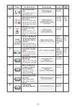
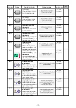
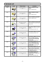
Page 88: ...n E011 External media not inserted External media is not inserted Possible to re enter after reset Previous screen E012 Read error Data read from external media cannot be performed Possible to re start after reset Previous screen E013 Write error Data write from external media cannot be performed Possible to re start after reset Previous screen E015 Format error Format cannot be performed Possible...

Page 89: ...server cannot be performed Possible to re start after reset Previous screen E029 Media slot release error Lid of media slot is open Possible to re start after reset Previous screen E030 Needle bar position missing error Needle bar is not in the predetermined position Turn hand pulley to bring needle bar to its predetermined position Data input screen E031 Air pressure drop Air pressure is dropped ...

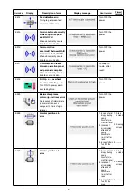
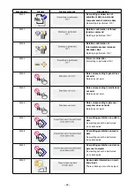
Page 90: ... E061 Memory switch data error Memory switch data is broken or revision is old Turn OFF the power E220 Grease up warning At the time of operation of 100 million stitches Refer to 1 13 Replenishing the designated places with grease p 101 Possible to re start after reset Data input screen E221 Grease up error At the time of operation of 120 million stitches The sewing machine is put in the sewing im...

Page 91: ...ype code of system is not proper in the initial communication Possible to rewrite program after pressing down communication switch Communi cation screen E704 Inconsistency of system version System software version is inconsistent in the initial communication Possible to rewrite program after pressing down communication switch Communi cation screen E730 Main shaft motor encoder defectiveness When e...

Page 92: ... fluctuates more than 15 Turn OFF the power E905 Heat sink temperature for SERVO CONTROL p c b abnormality Turn ON the power again after taking overheat time of SERVO CONTROL p c b Turn OFF the power E907 X feed motor origin retrieval error When origin sensor signal is not inputted at the time of origin retrieval motion Turn OFF the power E908 Y feed motor origin retrieval error When origin sensor...

Page 93: ...reset E918 MAIN p c b overheat Overheat of MAIN p c b Turn ON the power again after taking time Turn OFF the power E925 Intermediate presser motor origin retrieval error Origin sensor of intermediate presser motor does not change at the time of origin retrieval Turn OFF the power E926 X motor position slip error 1 In case of error display during sewing Possible to re start after reset 2 In case of...

Page 94: ...rn OFF the power E932 Y motor overload error Turn OFF the power E933 Thread trimming motor overload error Turn OFF the power E935 Intermediate presser motor overload error Turn OFF the power E936 X Y motor out of range error Turn OFF the power E943 MAIN CONTROL p c b trouble When data writing to MAIN CONTROL p c b cannot be performed Turn OFF the power E946 HEAD RELAY p c b trouble When data writi...

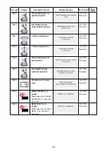
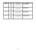
Page 95: ...ting confirmation of media Overwriting is performed OK M530 Overwriting confirmation of vector data of panel M3 data sewing standard format data simplified program data Overwriting is performed OK M531 Overwriting confirmation of vector data of media M3 data sewing standard format data simplified program data Overwriting is performed OK M532 Overwriting confirmation of vector data on personal comp...

Page 96: ...OK M544 Data corresponding to panel does not exist Data does not exist M545 Data corresponding to media does not exist Data does not exist M546 Data corresponding to personal computer does not exist Data does not exist M547 Overwriting prohibition on pattern data Overwriting cannot be performed since data exists M548 Overwriting prohibition on media data Overwriting cannot be performed since data ...

Page 97: ...lay Display message Description M653 During formatting Formatting is performed M669 During data reading Data is being read M670 During data writing Data is being written M671 During data converting Data is being converted ...

Page 98: ...nt lower than 22 1 2 Adjusting the needle to shuttle relation 5 Marker line for DP x 17 needle with needle count higher than 22 6 Marker line for DP x 17 needle with needle count lower than 22 3 When DP x 17 needle of which needle count is lower than 22 is used 3 When DP x 17 needle of which needle count is higher than 22 is used Turn ON the power once and turn OFF the power again after making the...

Page 99: ...t Then tighten setscrew 8 4 Loosen shuttle race screw 4 and adjust the longitudinal position of the shuttle race To do this adjustment turn shuttle race adjust ing shaft 5 clockwise or counterclockwise to provide a 0 05 to 0 1 mm clearance between needle 2 and the blade point of shuttle 1 5 After adjusting the longitudinal position of shut tle race further adjust to provide a 7 5 mm clearance betw...

Page 100: ... hook driving shaft positioning shaft 2 13704705 supplied with the machine as accessories from the hole on the machine bed side 3 Turn the main shaft in the normal direction with the hand pulley set the needle bar to its upper dead point and tighten main shaft sprocket setscrews 1 4 Draw out hook driving shaft positioning shaft 2 turn the main shaft in the normal direction with the hand pulley and...

Page 101: ...presser in the lowered state 1 Remove face cover 2 Turn handwheel to make the needle bar come down to its lowest point 3 Loosen hinge screw 1 and move it to the di rection A to increase the stroke 4 When marker dot A is aligned with the right side of the outer periphery of washer 2 the vertical stroke of the intermediate presser becomes 4 mm And when marker dot B is aligned with the right side of ...

Page 102: ...sen screw 3 Adjust so that thread breakage de tector plate 1 does not touch any adjacent metallic parts other than thread take up spring 2 2 3 1 1 6 The moving knife and counter knife 1 0 mm 1 Loosen adjusting screw 1 so that a clearance of 18 5 mm is provided between the front end of the throat plate and the top end of thread trimmer lever small 3 To adjust move the moving knife in the direction ...

Page 103: ...ection 15A time lag fuse 2 For solenoid and pulse motor power supply protection 3 15A time lag fuse 3 For control power supply protection 2A fast blow type fuse 1 Loosen setscrew 1 and remove setscrew 1 2 When screwing in adjustment screw 2 the amount of oil of oil pipe left 4 can be reduced 3 After the adjustment screw in setscrew 1 and fix it 1 The state of standard delivery is the position wher...

Page 104: ...imp style terminal of AC input cord to the power plug as shown in the figure Caution Securely perform the insulation treatment to the red terminal which is not used with insulation tape or the like When the insulation is insufficient there is a danger of electric shock or leakage current C In case of using with single phase 200V to 240V Changing the changeover connector Connect to 200V the 100 200...

Page 105: ...replenishing the places with grease after the display of error No E220 error E221 Grease up error is displayed and the sewing machine fails to operate since the error cannot be released even when the RESET key is pressed When error E221 Grease up error is displayed be sure to replenish the designated places below with grease Then call the memory switch U245 press CLEAR button A and set NUMBER OF S...

Page 106: ...mediate presser link hinge screw with grease 2 Replenishing the face plate section needle bar intermediate presser bar guide bar with grease 1 Take out grease 40006323 light blue sup plied with the unit 2 Open the face cover 3 Replenish needle bar intermediate presser bar and guide bar with the grease WARNING Turn OFF the power before starting the work so as to prevent accidents caused by abrupt s...

Page 107: ...high 7 The synthetic fiber thread melts due to heat generated on the needle 8 When taking up thread thread is pierced with needle tip Take it out and remove the scratches us ing a fine whetstone or buff Buff or replace it Adjust the position of the work clamp Take out the shuttle and remove the fibrous dust from the shuttle race Reduce the needle thread tension Reduce the tension Use silicone oil ...

Page 108: ...e presser 8 Threads break at time of thread trimming 1 The moving knife has been im properly position Correct the position of the moving knife 98 9 The thread clamp is entangled with needle thread 1 The needle thread at the sewing start is too long Tighten thread tension controller No 1 and make the length of needle thread 40 to 50 mm 14 10 Uneven length of the needle thread 1 The tension of threa...

Page 109: ...r knits OP 11 to 14 B242621000A ø 1 6 For light weight to medium weight materials 14 to 18 1 B242621000B ø 2 0 For medium weight to heavy weight materials H type 18 to 21 B242621000D ø 2 4 For heavy weight materials OP B242621000F ø 3 0 For heavy weight materials G type 22 to 25 2 B242621000G ø 3 0 with a counterbore For extra heavy weight materials OP supplied for G type 18 to 25 B242621000H ø 3 ...

Reviews: