


– 12 –
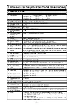
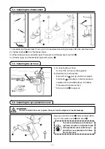
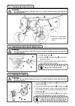
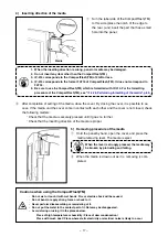
4-8. adjusting the thread take-up spring
3
2
1
4
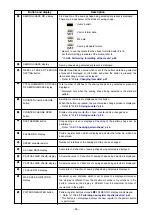
1) Adjustng the stroke
Loosen setscrew
2
, and turn thread tenson asm.
3
.
Turnng t clockwse wll ncrease the movng
amount and the thread drawng amount wll
ncrease.
2) Adjustng the pressure
To change the pressure of the thread take-
up sprng
1
, nsert a thn screwdrver nto the
slot of thread tenson post
4
whle screw
2
s
tghtened, and turn t. Turnng t clockwse wll
ncrease the pressure of the thread take-up
sprng. Turnng t counterclockwse wll de-
crease the pressure.
Decrease
Increase
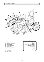
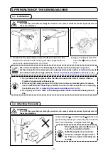
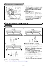
5. oPEratIoN oF tHE SEWING MacHINE
A
B
C
1)
2)
3)
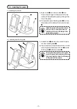
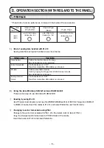
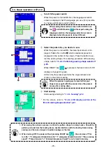
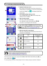
5-1. Sewing
[In case of the mechanical valve pedal]
1) Set a workpece under the feedng frame and
depress pedal
A
of the pedal swtch. Then the
feedng frame comes down.
When the foot s detached, the feedng frame
returns to ts home poston.
The lowerng speed of the feedng frame
changes accordng to the depressng amount.
Ths s used when postonng the parts.
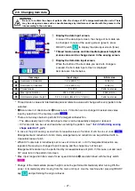
2) When postonng the workpece and depress-
ng pedal
B
, the feedng frame comes down to
the bottom and holds the workpece.
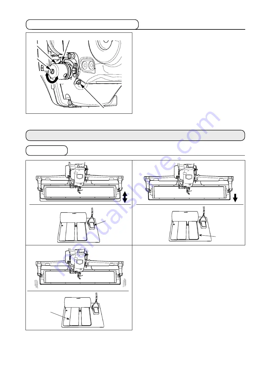
3) Depress pedal
C
when the feedng frame
comes down to the bottom and sewng starts.
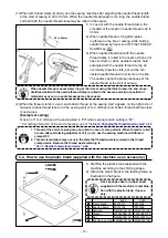
[For the 2-step stroke pedal (PK47)]