background image


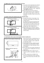
 If the clearance between the blade point of hook and the needle is smaller than the specified 

value, the blade point of hook will be damaged.  If the clearance is larger, stitch skipping will 

result.

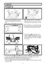
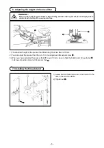
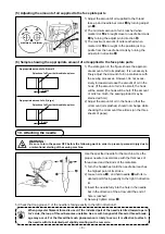
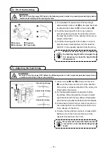
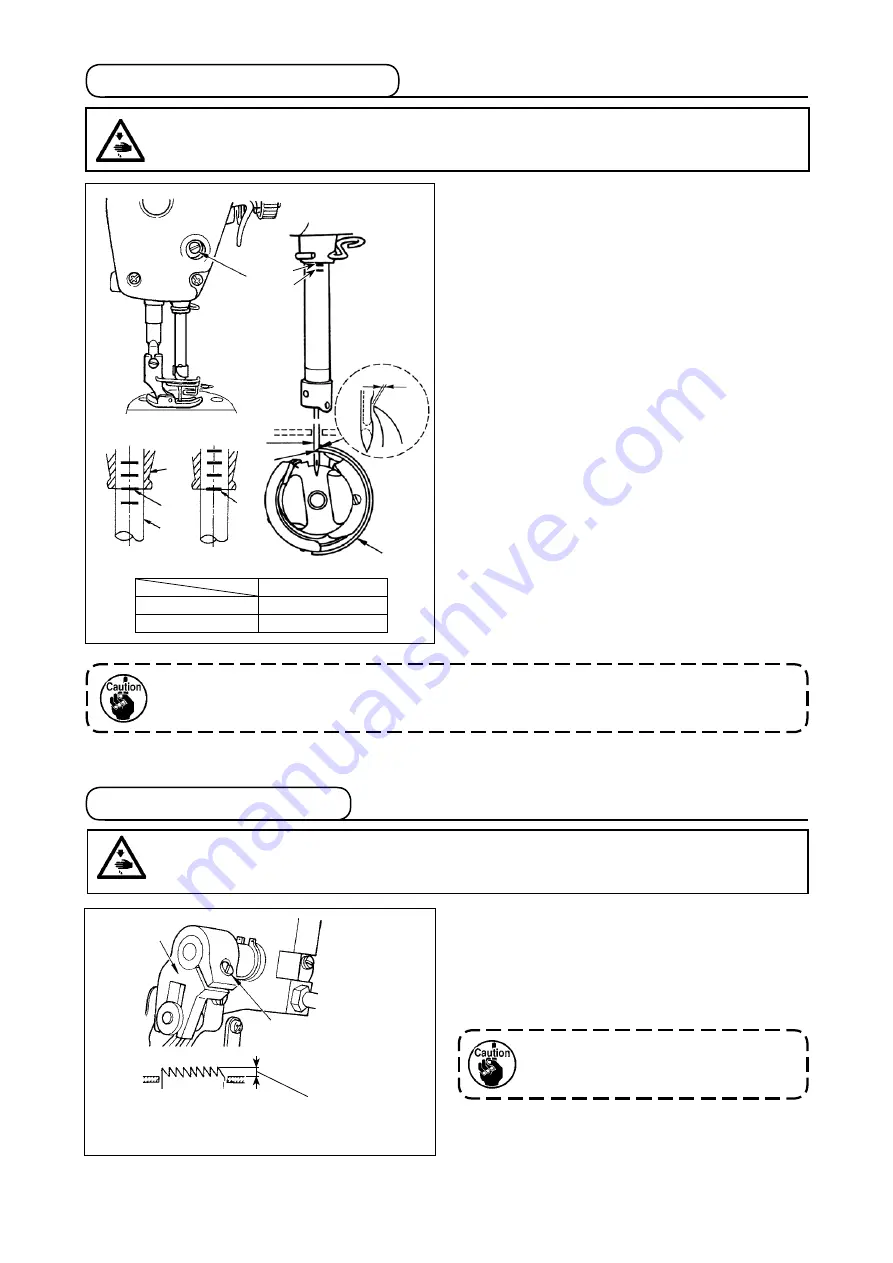
To adjust the height of the feed dog :

 Loosen  screw 

 of crank 

.

 Move the feed bar up or down to make adjust-

ment.

 Securely tighten screw 

.


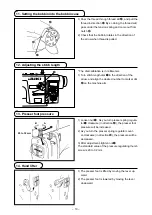
If the clamping pressure is insufficient, 

the motion of the forked portion becomes 
heavy.

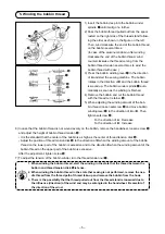
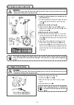
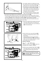
(1) Adjust the timing between the needle and the 

hook as follows : 

1) Turn the handwheel to bright the needle bar down 

to the lowest point of its stroke, and loosen set-
screw 

(Adjusting the needle bar height)

2) Align marker line 

A

 on needle bar 

 with the 

bottom end of needle bar lower bushing  

, then 

tighten setscrew 

.

(Adjusting position of the hook 

a

)

3) Loosen the three hook setscrews, turn the hand-

wheel and align marker line 

B

 on ascending nee-

dle bar 

 with the bottom end of needle bar lower 

bushing 

.

4) After making the adjustments mentioned in the 

above steps, align hook blade point 

 with the 

center of needle 

. Provide a clearance of 0.04 

mm to 0.1 mm (reference value) between the nee-
dle and the hook, then securely tighten setscrews 
in the hook.

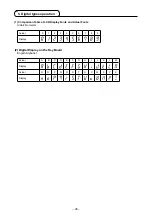
 20. Needle-to-hook relationship

  21. Height of the feed dog
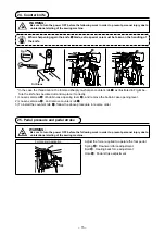
WARNING :

Be sure to turn the power OFF before the following work in order to prevent personal injury due to 

unintentional starting of the sewing machine.

WARNING :

Be sure to turn the power OFF before the following work in order to prevent personal injury due to 

unintentional starting of the sewing machine.

Dimension D (mm)

DDL-7000AS-7

0.04 to 0.10

DDL-7000AH-7

0.12 to 0.20

0.75 to 0.85 mm (DDL7000AS-7)
1.15 to 1.25 mm (DDL7000AH-7)

a

A

B

D

A

B

– 13 –

Summary of Contents for DDL-7000A-7 Series

Page 1: ...DDL 7000A 7 Series INSTRUCTION MANUAL ...

Page 2: ...Needle to hook relationship 13 21 Height of the feed dog 13 22 Tilt of the feed dog 14 23 Adjusting the feed timing 14 24 Counter knife 15 25 Pedal pressure and pedal stroke 15 26 Adjustment of the pedal 16 27 Marker dots on the handwheel 16 III FOR THE OPERATOR 17 1 Operating procedure of the sewing machine 17 2 Operation panel built in the machine head 19 3 Operating procedure of the sewing patt...

Page 3: ...e system Main shaft direct drive system 13 Electrical box Integral with the machine head 14 Power switch 3 phase CE 15 Motor used AC servomotor 550 W 16 External dimensions Distance from machine arm to needle 260 mm height of the machine arm 130 mm Arm size 432 mm x 105 mm bed size 476 mm x 178 mm Entire length 603 mm 17 Operating temperature humidity range Temperature 5 C to 35 C Humidity 35 to 8...

Page 4: ... the sewing machine while holding the machine arm with two persons as shown in the figure Caution Never hold the handwheel since it rotates 2 Place the sewing machine on a horizontal and plane place when placing it and do not place any protruding thing such as a screwdriver or the like 3 Adjust so that the oil pan is supported at the four corners of the table Mount rubber hinge seat on the table a...

Page 5: ... it can start abruptly inviting the risk of personal injury To prevent personal injury caused by maloperation be sure to lock the connector with lock Do not connect the power plug until the connection of cords is completed Fix the cords while taking care not to forcibly bend them or excessively clamp them with staples As for the details of handling respective devices read carefully the Instruction...

Page 6: ...e of pedal lever with nut WARNING To protect against possible personal injury due to abrupt start of the machine be sure to start the following work after turning the power off and a lapse of 5 minutes or more 4 Attaching the connecting rod ...

Page 7: ...ease To the direction of B Increase 6 In case that the bobbin thread is not wound evenly on the bobbin remove the handwheel loosen screw and adjust the height of bobbin thread tension It is the standard that the center of the bobbin is as high as the center of thread tension disk Adjust the position of thread tension disk to the direction of D when the winding amount of the bobbin thread on the lo...

Page 8: ...d using the knee lifter is 10 mm 2 You can adjust the presser foot lift up to 13 mm using knee lifter adjust screw 3 When you have adjusted the presser foot lift to over 10 mm be sure that the bottom end of needle bar in its lowest position does not hit presser foot WARNING Be sure to turn the power OFF before the following work in order to prevent personal injury due to unintentional starting of ...

Page 9: ...0CA 3 Be sure to lubricate clean oil 4 When the oil surface is lower than the LOW mark the oiling may be inconsistent To prevent inconsistent oiling add oil before the oil surface comes down to reach the LOW mark Amount of oil oil splashes confirmation paper Position to confirm the amount of oil oil splashes Oil splashes confirmation paper 3 10 mm 25 mm 70 mm When carrying out the procedure descri...

Page 10: ...e run idle for ap proximately 30 seconds to check the amount of oil in the hook 2 Adjusting the amount of oil oil spots in the hook 3 Sample showing the appropriate amount of oil in the hook Splashes of oil from the hook Amount of oil oil splashes confirmation paper Position to confirm the amount of oil oil splashes Oil splashes confirmation paper 25 mm 70 mm 4 Confirmation of the amount of oil su...

Page 11: ...hread take up lever 1 mm Appropriate amount of oil large Appropriate amount of oil small 2 mm Splashes of oil from the thread take up lever 5 Adjusting the amount of oil supplied to the face plate parts 10 Attaching the needle WARNING Be sure to turn the power OFF before the following work in order to prevent personal injury due to unintentional starting of the sewing machine C D B A Use the speci...

Page 12: ...ation is in millimeters 1 Turn stitch length dial in the direction of the arrow and align the desired number to marker dot A on the machine arm 1 Loosen nut As you turn presser spring regula tor clockwise in direction A the presser foot pressure will be increased 2 As you turn the presser spring regulator count er clockwise in direction B the pressure will be decreased 3 After adjustment tighten n...

Page 13: ...ht of the presser bar 16 Threading the machine head WARNING Be sure to turn the power OFF before the following work in order to prevent personal injury due to unintentional starting of the sewing machine WARNING Be sure to turn the power OFF before the following work in order to prevent personal injury due to unintentional starting of the sewing machine 11 ...

Page 14: ... counterclock wise in direction D 2 Adjusting the bobbin thread tension 1 The bobbin thread tension is increased by turning tension regulating screw clockwise in direction E 2 It is decreased by turning the screw counterclock wise in direction F 17 Thread tension 18 Thread take up spring 19 Adjusting the thread take up stroke WARNING Be sure to turn the power OFF before the following work in order...

Page 15: ...djusting position of the hook a 3 Loosen the three hook setscrews turn the hand wheel and align marker line B on ascending nee dle bar with the bottom end of needle bar lower bushing 4 After making the adjustments mentioned in the above steps align hook blade point with the center of needle Provide a clearance of 0 04 mm to 0 1 mm reference value between the nee dle and the hook then securely tigh...

Page 16: ... dot A on the feed bar shaft is aligned with marker dot B on feed rocker 2 To tilt the feed dog with its front up in order to prevent puckering loosen the setscrew and turn the feed bar shaft 90 in the direction of the arrow using a screwdriver 3 To tilt the feed dog with its front down in order to prevent uneven material feed turn the feed bar shaft 90 in the opposite direction from the arrow Whe...

Page 17: ...e adjustment For General Application B C A 25 Pedal pressure and pedal stroke WARNING Be sure to turn the power OFF before the following work in order to prevent personal injury due to unintentional starting of the sewing machine Oil Stone Fig A In the case the thread cannot be trimmed sharply re sharpen counter knife as illustrated in Fig A be fore the knife has become dull and re place it correc...

Page 18: ...nt of the pedal WARNING Be sure to turn the power OFF before the following work in order to prevent personal injury due to unintentional starting of the sewing machine 27 Marker dots on the handwheel The upper stop position of the needle bar is the po sition at which marker dot on the cover is aligned with white marker dot on the handwheel With respect to the operating timing of the thread trimmin...

Page 19: ...ying out the aforementioned steps it is necessary to wait for five minutes or more after you have turned OFF power switch 3 Do not place your hand or anything under the needle since the needle bar may automatically move according to the memory switch setting when you turn ON the power to the sewing machine 2 When you depress the back part of pedal the needle bar and the presser lifting motor carry...

Page 20: ...s changed in repetition 3 The pedal is operated in the following four steps a The machine runs at low sewing speed when you lightly depress the front part of the pedal b The machine runs at high sewing speed when you further depress the front part of the pedal If the automatic reverse feed stitching has been preset the machine runs at high speed after it completes reverse feed stitching c The mach...

Page 21: ... the maximum sewing speed Long time Continuous input is possible by keeping the key held pressed for three seconds or more Z Short time This key is used to add one stitch to the number of reverse feed stitches at the beginning and end of sewing process A Long time Continuous input is possible Z Short time This key is used to subtract one stitch from the number of reverse feed stitches at the begin...

Page 22: ... the end of sew ing to Reverse feed stitching Double reverse feed stitching Disable K Short time Used to set the type of stitching to free stitching L Short time This key is used to set the sewing mode to the constant dimension sewing straight line M Short time Used to set the type of stitching to overlapped stitching N Q Short time Used to change over the constant dimension stitching pattern Y Sh...

Page 23: ...e reverse feed stitching disable by pressing The reverse feed stitching pattern at the end of sewing can be changed over to enable double reverse feed stitching disable by pressing The current setting state of the reverse feed stitching is displayed on the display section I and J 2 Change the number of stitches to be sewn in tar get process A B C D with to The number which exceeds 9 is indicated a...

Page 24: ...itches D Number of times of repetition 0 to 15 times 1 When process D is set to 5 times the sewing is repeated as A B C B C 2 The number which exceeds 9 is indicated as follows A 10 b 11 c 12 d 13 E 14 and F 15 Setting procedure of the overlapped stitching 1 Press to enable the overlapped stitching pattern When the overlapped stitching pattern is enabled is displayed in the display section C 2 Cha...

Page 25: ...ng pattern is enabled is displayed on the display portion L Immediately after the constant dimension stitching is enabled the numbers of reverse feed stitching processes A B C and D are displayed on the display section Z 2 When is pressed the content shown on display section Z is changed over to the number of stitches for the constant dimension stitching The number of stitches 0 to 999 for the con...

Page 26: ... Z 2 When switch is pressed the display section A and B changes its display to the num ber of stitches for the constant dimension stitching process EF is displayed The number of stitches for the process EF can be set by pressing 3 Then the content shown on display section Ⓐ is changed over to the number of stitches for the constant dimension stitching process GH by pressing switch The number of st...

Page 27: ...seams P5 Set the number of stitches to 0 zero The number of stitches 0 zero means termi nation of the polygonal shape stitching After that four thread polygonal shape stitching is carried out For the initial setting the number of steps is set to four and the number of stitches for each step is set to 12 stitches After the setting confirm the data you have entered with Number of seams number of sti...

Page 28: ... power switch when ten or more seconds have passed af ter turning it OFF If the power switch is re turned ON immediately after turning it OFF the sewing machine may fail to operate normally In such a case be sure to turn ON the power switch again properly 2 To change the function setting number press to and change it to a desired one 3 After having changed the function setting number to a desired ...

Page 29: ...er A If is pressed before confirming the data the operation being carried out will be cancelled and the screen will return to the previous screen The current set value maximum number of revo lutions of function setting number P 01 is dis played Change the maximum number of revolu tions with to and confirm the set value Then confirm the setting with switch B If is pressed before confirming the data...

Page 30: ...ison Table of LCD Display Fonts and Actual Fonts Arabic Numerals Actual 0 1 2 3 4 5 6 7 8 9 Display Actual A B C D E F G H I J K L M Display Actual N O P Q R S T U V W X Y Z Display 2 Digital Display on the Key Board English Alphabet 28 ...

Page 31: ... performed at the sewing speed set with P04 Reverse feed stitching speed at the beginning of sewing U 0 1 1 1 P13 Function of stop immedi ately after the reverse feed stitching at the beginning of sewing Operation to be carried out at the end of the reverse feed stitch ing at the beginning of sewing is selected with this function setting item CON The sewing machine does not stop temporarily after ...

Page 32: ... Initialization of data Machine head type is selected with this function setting item 2 DDL 7000AS 7 3 DDL 7000AH 7 When you select the corresponding machine head and press the enter switch all existing data are initialized to the initial values for the machine head you have selected S 2 3 2 3 P77 Back tack solenoid ON timing at the end of sewing The BT solenoid ON timing at the end of sewing is s...

Page 33: ... feed stitching on the way is set with this function setting item U 200 3000 sti min 1900 1900 P163 Ending angle of soft start for the thread clamp The ending angle of the soft start for the thread clamp is set with this function setting item Refer to the explanation of operation of the thread clamp solenoid in the Engineer s Manual for details U 0 720 340 340 P166 1st electric current time for th...

Page 34: ...meter Press to select the parameter code P04 Then press to enter Function setting data Press to key to adjust the Start Back Tacking Speed After adjustment press to save value 7 Details of setting of the main functions How to set Maximum Sewing Speed 1 In following parameter operation key it will display corresponding speed value 2 In following function after value changed press key to save the va...

Page 35: ...o adjust End Back Tacking speed After adjustment press to save value How to set Bar Tacking Speed Press to enter user parameter Press to select the parameter code P06 Then press to enter Function setting data Press to to adjust the Bar Tacking Speed After adjustment press to save value How to set End Back Tacking Speed 33 ...

Page 36: ...t Stitch Sewing Speed Press to enter user parameter Press to select the parameter code P09 Then press to enter Function setting data Press to to adjust Constant Stitch Sewing speed After adjustment press to save value 34 ...

Page 37: ...stitches and thread trimming command can be added to the touch back switch on the sewing machine head Function setting No 139 Function of reverse feed stitching on the way is selected 9 1 3 0 OFF Normal back tack function 1 ON Function of reverse feed stitching on the way Function setting No 140 Number of stitches performing reverse feed stitching is set 0 1 4 Setting range 0 to 19 stitches Functi...

Page 38: ... of the pedal automatic thread trimming is performed after reverse feed stitching as many as the number of stitches specified by the function setting No P140 has been performed Actions under each setting state Used as the normal reverse feed stitching touch back switch Used for reinforcing seam press sewing of the pleats It works only while the sewing machine is in operation Used for reinforcing s...

Page 39: ...sser motor Operates when the back part of pedal is depressed 1 Needle bar goes up to its upper position and the presser motor automatically goes up after automatic origin retrieval 2 Needle bar automatically goes up to its upper position and the presser motor comes down after automatic origin retrieval Setting of the operation of needle up down switch after thread trimming Function setting No P118...

Page 40: ... Normal A and shorter B Adjustment P19 Increase the set value B becomes longer Start point Start point Start point Start point How to balance stitches for Start Back Tacking Function setting Nos P18 and P19 Example Step 1 Setting stitch number for Start Back Tacking A and B 3 Step 2 Sewing the pattern in normal speed Step 3 If unbalanced situation is appeared please correct it as below Suggestion ...

Page 41: ...al C and longer D Adjustment P25 Decrease the set value C becomes longer and D becomes shorter Case 6 Normal C and shorter D Adjustment P25 Increase the set value C becomes shorter and D becomes longer Start point Start point Start point Start point Start point Start point How to balance stitches for End Back Tacking Function setting Nos P25 P27 and P77 Example Step 1 Setting stitch number for End...

Page 42: ... and longer B Adjustment P33 Decrease the set value B becomes shorter Case 4 Normal A and shorter B Adjustment P33 Increase the set value B becomes longer Start point Start point Start point Start point How to balance stitches for Bar Tacking Function setting Nos P32 and P33 Example Step 1 Setting stitch number for Bar Tacking A B 4 and turns of Bar Tacking D 4 Step 2 Sewing the pattern in normal ...

Page 43: ... select the corre sponding machine head Set value 2 DDL 7000AS 7 Set value 3 DDL 7000AH 7 3 Data is initialized by pressing Then the sewing machine returns to the normal sewing state If you want to initialize the data change the setting of the type of machine head to a different type then select the desired type of machine head Example In the case the selected type of machine head is 2 P70 Change ...

Page 44: ...f functions p 26 Confirm the data with 2 Press to to set the bobbin counter value B When the bobbin counter reaches the bobbin counter value x 10 the bobbin count complete screen is displayed 3 Press to determine the set value and return the sewing machine to the normal sewing state 4 Carry out sewing When the bobbin counter value becomes 0 zero the count complete screen is displayed C When you pr...

Page 45: ...forementioned data 1 Press under the normal sewing state to display the function setting screen Refer to II 4 Setting of functions p 26 Confirm the data with You may select any function setting number 2 On the screen that you can operate the function setting data keep held pressed for three seconds Then the function setting data being displayed is saved and the SAVE screen A is displayed for a mom...

Page 46: ...pressed all of the function set ting data saved in the steps of procedure 1 and 2 are initialized and the entire screen display of LCD C is displayed for a moment Then the sewing machine returns to the normal sewing state 5 Data initialization is cancelled by pressing Then the sewing machine returns to the nor mal sewing state B C ...

Page 47: ... is displayed before display ing the function setting screen by pressing in the normal sewing state B 7 Enter the four digit password set with Function setting No J14 using to 8 The function setting screen is displayed by press ing On this screen the functions can be set 1 Turn the power ON while keeping or or and held pressed simultaneously This function is activated under the service level 2 Pre...

Page 48: ...ers the USB connector a failure can be caused Insertion position of the USB thumb drive WARNING The device to be connected to the USB port should have the rated current value or less as shown below If any device rated current value of which is higher than the rated current value the main body of the sewing machine or the USB device connected can be damaged or malfunction Rated current value of the...

Page 49: ...rmal Check whether the sewing speed is set extremely high E 08 Reverse feed stitching lever operation time is exceeded Turn the OFF Then re turn ON the power E 09 E 11 Encoder Z phase detection fault Turn the power OFF Check the connection of the motor en coder cable to the connector E 10 Solenoid overcurrent Turn the power OFF Check whether the solenoid has failed E014 Encoder AB phase detection ...

Reviews: