background image

– 6 –

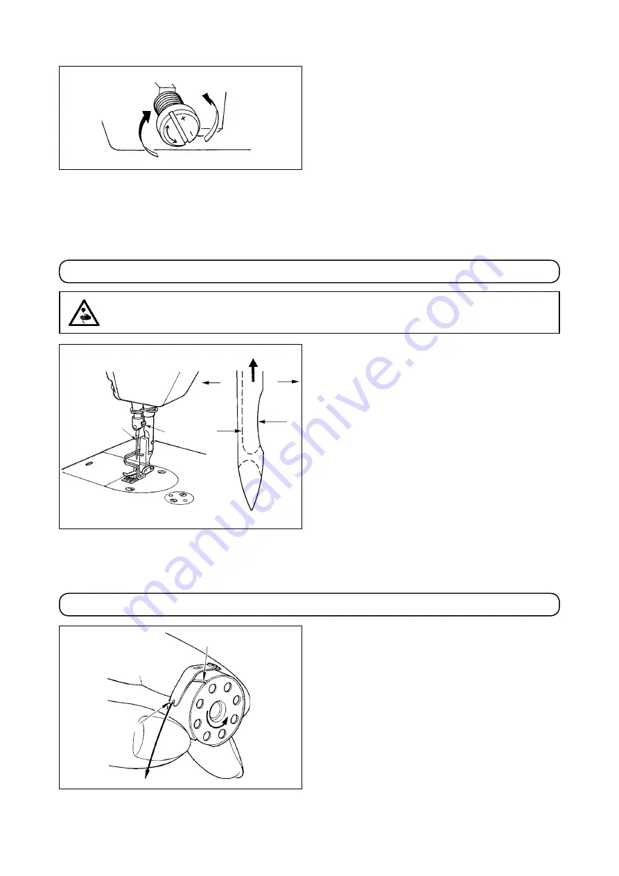
adjusting the amount of oil (oil spots) in the hook

)  Turnng the ol amount adjustment screw attached 

on the hook driving shaft front bushing in the “+” 

drecton (n drecton 

A

) wll ncrease the amount 

of oil (oil spots) in the hook, or in the “–” direction 

(n drecton 

B

) wll decrease t.

2)  After the amount of ol n the hook has been 

properly adjusted wth the ol amount adjustment 
screw, make the sewng machne run dle for ap

-

proximately 30 seconds to check the amount of 

ol n the hook.

A needle of DBx1 should be used. Select a proper 

needle sze accordng to the count of thread and the 
type of materal used.
)  Turn the handwheel untl the needle bar reaches 

the hghest pont of ts stroke.

2)  Loosen screw 

2

, and hold needle 

1

 wth ts n

-

dented part 

A

 facing exactly to the right in direc-

ton 

B

3)  Insert the needle fully nto the hole n the needle 

bar n the drecton of the arrow untl the end of 
hole s reached. 

4)  Securely tighten screw 

2

5)  Check that long groove 

C

 of the needle s facng 

exactly to the left in direction 

D

.

 8. attacHInG tHE nEEDLE

 9. sEttInG tHE BoBBIn Into tHE BoBBIn casE

)  Install the bobbn n the bobbn case so that the 

thread wound drecton s counterclockwse. 

2)  Pass the thread through thread slt 

A

, and pull 

the thread n drecton 

C

.

  By so dong, the thread wll pass under the ten

-

son sprng and come out from notch 

B

3)  Check that the bobbn rotates n the drecton of 

the arrow when thread s pulled.

WarnInG :

to avoid possible personal injury due to abrupt start of the machine, turn off the power to the 

machine and check to be sure that the motor has totally stopped rotating in prior.

A

B

1

2

D

B

C

A

B

C

A

Summary of Contents for DDL-8100e

Page 1: ...DDL 8100e DDL 8100eH Instruction Manual ENGLISH ...

Page 2: ...HING THE NEEDLE 6 9 SETTING THE BOBBIN INTO THE BOBBIN CASE 6 10 ADJUSTING THE STITCH LENGTH 7 11 PRESSER FOOT PRESSURE 7 12 HAND LIFTER 7 13 ADJUSTING THE HEIGHT OF THE PRESSER BAR 7 14 THREADING THE MACHINE HEAD 8 15 THREAD TENSION 8 16 THREAD TAKE UP SPRING 9 17 ADJUSTING THE THREAD TAKE UP STROKE 9 18 NEEDLE TO HOOK RELATIONSHIP 10 19 HEIGHT OF THE FEED DOG 11 20 TILT OF THE FEED DOG 11 21 ADJ...

Page 3: ...le rubber hinge 2 be fore placing the machine head on cushions 3 on the four corners 2 INSTALLATION DDL 8100e DDL 8100eH Application General fabrics light weight and medium weight materials Medium weight materials heavy weight materials Sewing speed Max 4 500 sti min Max 4 000 sti min Stitch length Max 5 mm Needle DB x 1 9 to 18 DA x 1 20 to 23 Presser foot lift by knee lifter 10 mm standard 13 mm...

Page 4: ...d screw 5 with a tightening torque of 250 N cm If you tighten further these screws the securing state of the belt cover will not change 6 Fit cap 7 to the belt cover A 7 Move belt cover B 2 backward until the rubber section of belt cover B 2 comes in contact with belt cover A 3 Then further move the belt cover B in the same direction by 0 5 to 1 mm Now fix the belt cover B in position using wooden...

Page 5: ...oot 3 4 ADJUSTING THE HEIGHT OF THE KNEE LIFTER 5 INSTALLING THE THREAD STAND 1 Assemble the thread stand unit as illustrated in the figure shown on the left and insert it in the hole in the machine table 2 Tighten locknut 1 enough to fix the thread stand 3 For ceiling wiring pass the power cord through spool rest rod 2 WARNING To avoid possible personal injury due to abrupt start of the machine t...

Page 6: ...rate the machine after lubrication you will see splashing oil through oil sight window 2 if the lubrication is adequate 1 When you first operate your ma chine after setup or after an ex tended period of disuse run your machine at 3 000 sti min to 3 500 sti min for about 10 minutes for the purpose of break in 2 When the machine is continuously used at a low speed 2 000 sti min or less make the mach...

Page 7: ...AMOUNT OF OIL OIL SPLASHES IN THE HOOK Closely fit the paper against the wall surface of the bed Hook Hook driving shaft front bushing Bed Oil splashes confirmation paper 3 to 10 mm Approx 25 mm Approx 70 mm Sample showing the appropriate amount of oil 1 The amount of oil shown in the samples on the left should be finely adjusted in accordance with sewing processes Be careful not to excessively in...

Page 8: ...dle 1 with its in dented part A facing exactly to the right in direc tion B 3 Insert the needle fully into the hole in the needle bar in the direction of the arrow until the end of hole is reached 4 Securely tighten screw 2 5 Check that long groove C of the needle is facing exactly to the left in direction D 8 ATTACHING THE NEEDLE 9 SETTING THE BOBBIN INTO THE BOBBIN CASE 1 Install the bobbin in t...

Page 9: ...IFTER 1 To stop the machine with its presser foot up turn hand lifter 1 in direction A 2 The presser foot will go up about 5 5 mm and stop The presser foot will go back to its original posi tion when hand lifter is turned down in direction B 3 Using the knee lifter you can get the standard presser foot lift of about 10 mm and the maximum lift of about 13 mm 13 ADJUSTING THE HEIGHT OF THE PRESSER B...

Page 10: ...e bobbin thread tension 1 As you turn tension adjust screw 2 clockwise in direction C the bobbin thread tension will be in creased 2 As you turn screw 2 counterclockwise in direc tion D the bobbin thread tension will be de creased 14 THREADING THE MACHINE HEAD WARNING To avoid possible personal injury due to abrupt start of the machine turn off the power to the machine and check to be sure that th...

Page 11: ...st 3 counterclockwise in direction B the pressure will be decreased 17 ADJUSTING THE THREAD TAKE UP STROKE 1 When sewing heavy weight materials move thread guide 1 to the left in direction A to increase the length of thread pulled out by the thread take up 2 When sewing light weight materials move thread guide 1 to the right in direction B to decrease the length of thread pulled out by the thread ...

Page 12: ...r 2 upward its engraved marker line B is aligned with the lower end of needle bar lower bushing 3 4 After making the adjustments mentioned in the above steps align hook blade point 5 with the center of needle 4 Provide a clearance of 0 04 mm to 0 1 mm 0 06 to 0 12 mm for DDL 8100eH reference value between the needle and the hook then securely tighten setscrews in the hook 0 04 to 0 1 mm 1 2 3 4 5 ...

Page 13: ...y 90 as standard 2 To tilt the feed dog with its front up in order to pre vent puckering loosen the setscrew and turn the feed bar shaft 90 in the direction of the arrow using a screwdriver 3 To tilt the feed dog with its front down in order to prevent uneven material feed turn the feed bar shaft 90 in the opposite direction from the arrow The standard tilt for DDL 8100eH Whenever the feed dog til...

Page 14: ...e throat plate 3 To advance the feed timing in order to prevent uneven material feed move the feed eccentric cam in the direction of the arrow 4 To delay the feed timing in order to increase stitch tightness move the feed eccentric cam in the op posite direction from the arrow Be careful not to move the feed eccen tric cam too far or else needle break age may result 21 ADJUSTING THE FEED TIMING WA...

Reviews: